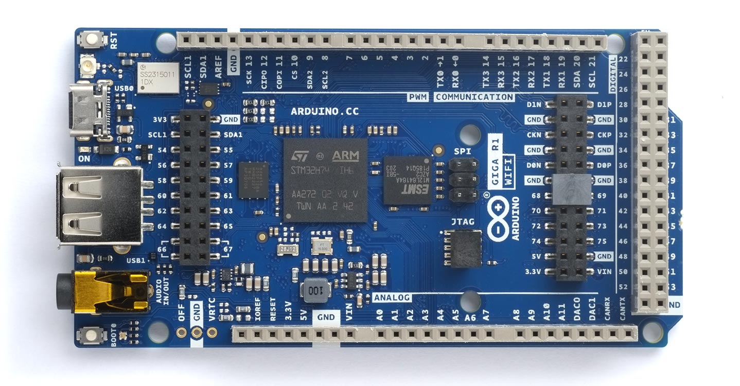
Arduino GIGA R1
I have a beta version of ARM uLisp running on an Arduino GIGA. However, I haven't included this among the officially supported boards because of some unsolved problems, which I hope will be fixed in future versions of the Arduino core. The following features don't currently work:
- Saving images to flash memory with save-image.
- Running machine-code programs in RAM with defcode.
- Full support of the Wi-Fi extensions.
Introduction
The Arduino GIGA is based on an STMicroelectronics STM32H747XI microcontroller, which consists of two cores: a Cortex-M7 at 480 MHz and a Cortex-M4 at 240 MHz:
It's the same processor featured in the Arduino Portenta H7 range, but in the Arduino Mega/Due form factor.
It includes a Murata 1DX for wireless communication, four UARTs, three I2C ports, two SPI ports, and a CAN port (needs an external transceiver). It has the same form factor as the Arduino Mega and Arduino Due, and so could support the same shields. There's an OFF pin so you can shut down the board, and a VRTC pin so you can connect a battery to keep the RTC running while the board is off.
In addition to the header sockets that give access to the 76 digital I/O pins, 12 analogue inputs, 12 PWM analogue outputs, and two DACs, it provides the following connectors:
- A USB-A connector suitable for hosting a USB stick, other mass storage devices, and HID devices such as a keyboard or mouse.
- A 3.5mm input-output jack connected to DAC0, DAC1, and A7.
- A 6-pin ISPC connector connected to SPI port 0.
- A USB-C connector to power and program the board, as well as simulate an HID device such as a mouse or keyboard.
- A JTAG connector.
- A 20 pin Arducam camera connector.
For details see the datasheet at ABX00063 Datasheet and the Arduino GIGA R1 Cheat Sheet.
Pinout
For the full pinout see ABX00063 Full Pinout.
Errors
If an error occurs in the MbedOS the GIGA flashes the red LED in a Morse-code pattern, and you'll need to reset the board. uLisp attempts to catch such errors before they occur.
LEDs
The Arduino GIGA has an RGB LED on pins 86 (red), 87 (green), and 88 (blue). Note that the LEDs are on when the output is low.
The green LED can be referred to as :led-builtin, so you can flash it with the following program:
(defun blink (&optional x)
  (pinmode :led-builtin :output)
  (digitalwrite :led-builtin x)
  (delay 1000)
  (blink (not x)))
Run it by typing:
(blink)
Exit from the program by entering ~.
Button
The Arduino GIGA provides a pushbutton labelled BOOT0 on pin 100. You can read this with the following program:
(defun button ()
  (pinmode 100 :input)
  (loop
   (print (digitalread 100))
   (delay 1000)))
Run it by typing:
(button)
Analogue inputs
The Arduino GIGA has analogue inputs on pins 76 (A0) to 85 (A13).
Analogue reference
You can provide an analogue reference for the ADCs on the AREF pin. The analogreference command is not supported.
Analogue outputs
The Arduino GIGA provides PWM outputs on pins 32 to 13 and 22 to 53. It also provides 12-bit DAC outputs on pin 84 (A12) and 85 (A13).
Serial
The Arduino GIGA has four serial ports:
| Port 0 (RX, TX) | Port 1 (RX, TX) | Port 2 (RX, TX) | Port 3 (RX, TX) |
| 0, 1 | 19, 18 | 17, 16 | 15, 14 |
SPI
The Arduino UNO R4 has two SPI ports:
- Port 0 on pin numbers 89 (MISO), 90 (MOSI), 91 (SCK), and 10 (CS) on the 6 pin header (ICSP) labelled SPI
- Port 1 on pin numbers 12 (MISO1), 11 (MOSI1), and 13 (SCK1) on the header sockets.
I2C
The Arduino GIGA provides three I2C ports, two of which are accessible from uLisp:
- Port 0 on pin numbers 20 (SDA) and 21 (SCL).
- Port 1 on pin numbers 102 (SDA) and 101 (SCL).
CAN Bus
The Arduino GIGA provides a CAN Bus port on pin numbers 93 (RX) and 94 (TX).

