Adafruit M0 boards
The Adafruit Gemma M0, Adafruit ItsyBitsy M0, and Adafruit Feather M0 boards are each based on the Microchip ATSAMD21, an ARM Cortex M0+ CPU with a 48 MHz clock. Each board provides 256 KB flash and 32 KB RAM.
These boards all have similar performance when running uLisp; for example, they run the Tak benchmark in 14 secs; see Performance.
Install the ARM version of uLisp for use with these boards.
Boards
Saving the workspace
All these boards allow you to save the entire workspace using save-image.
The ItsyBitsy and Feather M0 Express boards include a separate 2 MB SPI DataFlash chip, so this is used by uLisp for save-image.
On the Gemma M0 and Feather M0 boards save-image uses part of the flash on the ATSAMD21 chip.
Adafruit Gemma M0
The Adafruit Gemma M0 [1] is about the same size as a 50 pence piece. It has a limited selection of pins, but you can connect to them using alligator clip leads, making it ideal for students:
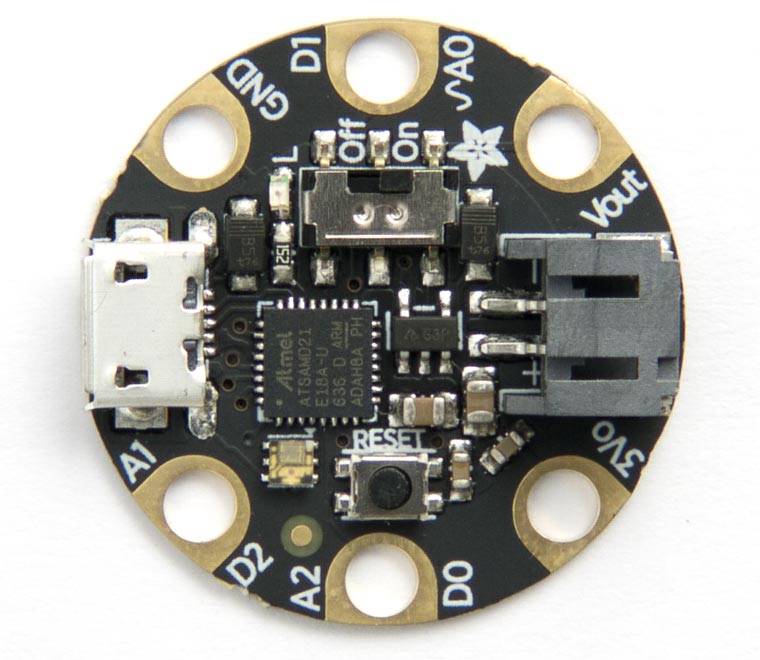
It includes a JST connector to allow you to power it from a Lipo battery.
I/O pins
Apart from the power pins it provides three multi-purpose pins:
| Label | Functions |
| D0/A2 | Digital I/O, analogue input, PWM, SDA, RX. |
| D1/A0 | Digital I/O, analogue input, DAC output. |
| D2/A1 | Digital I/O, analogue input, PWM, SCL, TX. |
LED
The Adafruit Gemma M0 has a red LED connected to the digital pin 13 which you can flash with the following program:
(defun blink (&optional x)
  (pinmode 13 t)
  (digitalwrite 13 x)
  (delay 1000)
  (blink (not x)))
Run it by typing:
(blink)
Exit from the program by entering ~.
DotStar RGB LED
The Adafruit Gemma M0 also has a DotStar (APA102) RGB LED mounted on the board. For more information about DotStar LEDs see Driving DotStar RGB LEDs.
Here's a program to set the LED to an arbitrary colour and brightness:
First we define variables for the clock and data pins; on the Gemma these are connected to Arduino pins 3 (data) and 4 (clock):
(defvar data 3)
(defvar clk 4)
Here's a routine to send a byte to the display, MSB first, toggling the clock pin after each bit:
(defun send (byte)
  (dotimes (i 8)
    (digitalwrite clk 0)
    (digitalwrite data (logand (ash byte (- i 7)) 1))
    (digitalwrite clk 1)))
Finally here's the function to send the appropriate stream of bits to the LED to define its colour and brightness:
(defun dotstar (bri blue green red)
  (pinmode clk t)
  (pinmode data t)
  (mapc send (list 0 0 0 0 (logior bri #xe0) blue green red #xff)))
To set the LED evaluate:
(dotstar bri blue green red)
where bri is the brightness (from 0 to 31), and blue, green, and red are the colour components, from 0 to 255. For example, this sets the LED to magenta (blue+red) at low brightness:
(dotstar 1 255 0 255)
Analogue inputs
The Adafruit Gemma M0 has three analogue inputs on pins 8 (A0) to 10 (A2). The resolution is 12 bits.
Analogue outputs
The Adafruit Gemma M0 has a DAC analogue output on pin 8.
Serial
The Adafruit Gemma M0 has one serial port on pin numbers 0 (TX) and 2 (RX).
SPI
The Adafruit Gemma M0 has one accessible SPI port: SPI0 on pin numbers 4 (MISO), 3 (MOSI), and 6 (SCK).
I2C
The Adafruit Gemma M0 has an I2C port on pin numbers 0 (SDA) and 2 (SCL).
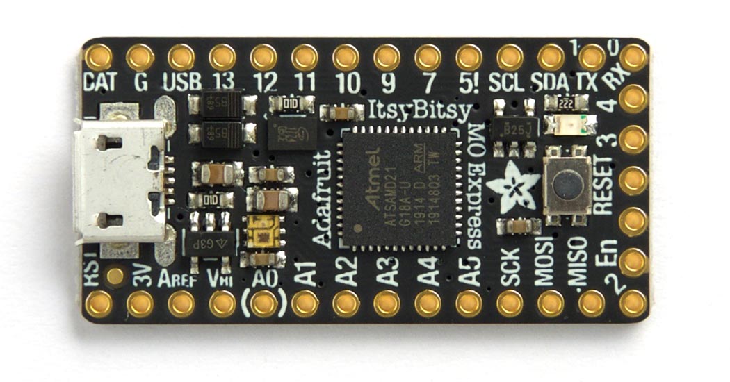
Adafruit ItsyBitsy M0
The Adafruit ItsyBitsy M0 [2] is the same size as Adafruit's other ItsyBitsy boards.
LEDs
The Adafruit ItsyBitsy M0 has a red LED connected to the digital pin 13 which you can flash with the following program:
(defun blink (&optional x)
  (pinmode 13 t)
  (digitalwrite 13 x)
  (delay 1000)
  (blink (not x)))
Run it by typing:
(blink)
Pin 13 can also be used as an analogue pin, so you can pulsate the red LED slowly on and off with the program:
(defun pulse ()
  (let (down)
    (loop
     (dotimes (x 256)
       (delay 5)
       (analogwrite 13 (if down (- 255 x) x)))
     (setq down (not down)))))
Run it by typing:
(pulse)
Exit from either program by entering ~.
DotStar RGB LED
The Adafruit ItsyBitsy M0 has a DotStar (APA102) RGB LED mounted on the board. For more information about DotStar LEDs see Driving DotStar RGB LEDs.
Here's a program to set the LED to an arbitrary colour and brightness:
First we define variables for the clock and data pins; these are connected to Arduino pins 40 (clock) and 41 (data):
(defvar clk 40)
(defvar data 41)
Here's a routine to send a byte to the display, MSB first, toggling the clock pin after each bit:
(defun send (byte)
  (dotimes (i 8)
    (digitalwrite clk 0)
    (digitalwrite data (logand (ash byte (- i 7)) 1))
    (digitalwrite clk 1)))
Finally here's the function to send the appropriate stream of bits to the LED to define its colour and brightness:
(defun dotstar (bri blue green red)
  (pinmode clk t)
  (pinmode data t)
  (mapc send (list 0 0 0 0 (logior bri #xe0) blue green red #xff)))
To set the LED evaluate:
(dotstar bri blue green red)
where bri is the brightness (from 0 to 31), and blue, green, and red are the colour components, from 0 to 255. For example, this sets the LED to magenta (blue+red) at low brightness:
(dotstar 1 255 0 255)
Analogue inputs
The Adafruit ItsyBitsy M0 has 12 analogue inputs on pins 14 (A0) to 25 (A11).
Analogue outputs
The Adafruit ItsyBitsy M0 has PWM analogue outputs on pins 3 to 6, 8 to 13, 15, 16, and 22 to 25, and a DAC output on pin 14.
Serial
The Adafruit ItsyBitsy M0 has a serial port on pin numbers 1 (TX) and 0 (RX).
SPI
The Adafruit ItsyBitsy M0 has an SPI port on pin numbers 28 (MISO), 29 (MOSI), and 30 (SCK).
I2C
The Adafruit ItsyBitsy M0 has an I2C ports on pin numbers 26 (SDA) and 27 (SCL).
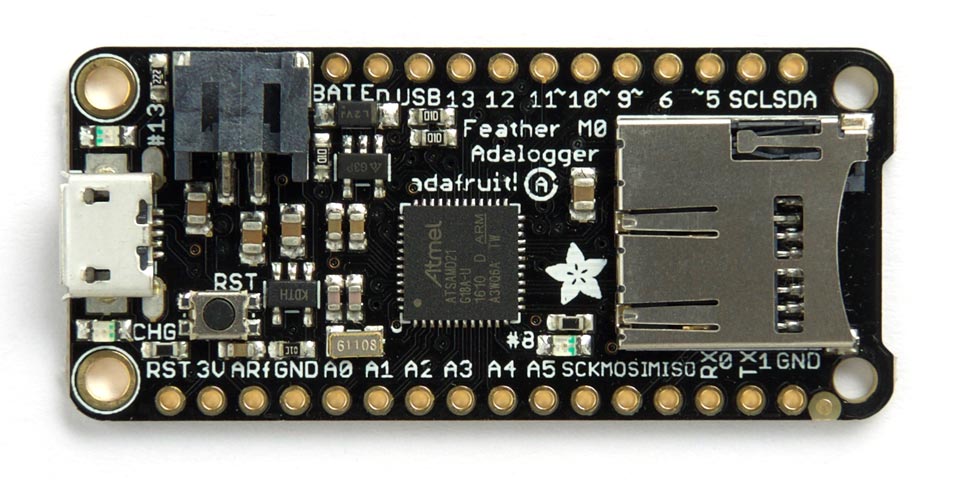
Adafruit Feather M0
Adafruit make three Feather M0 boards: the Feather M0 Basic Proto [3], the Feather M0 Adalogger [4] shown below which includes an SD Card socket, or the Feather M0 Express [5] which includes a DataFlash chip:
LED
The Adafruit Feather M0 has a red LED connected to digital pin 13 and a green LED connected to pin 8 which you can flash with the following program:
(defun blink (pin &optional x)
  (pinmode pin t)
  (digitalwrite pin x)
  (delay 1000)
  (blink pin (not x)))
To flash the green LED run:
(blink 8)
These pins can also be used as analogue pins, so you can pulsate the red LED slowly on and off with the program:
(defun pulse ()
  (let (down)
    (loop
     (dotimes (x 256)
       (delay 5)
       (analogwrite 13 (if down (- 255 x) x)))
     (setq down (not down)))))
Run it by typing:
(pulse)
Exit from either program by entering ~.
Analogue inputs
The Adafruit Feather M0 has eight analogue inputs on pins 14 (A0) to 19 (A5), and 44 (A6) and 45 (A7).
Serial
The Adafruit Feather M0 has a serial port on pin numbers 1 (TX) and 0 (RX).
SPI
The Adafruit Feather M0 has an SPI port on pin numbers 22 (MISO), 23 (MOSI), and 24 (SCK).
I2C
The Adafruit Feather M0 has two I2C ports: Wire0 on pin numbers 24 (SDA) and 25 (SCL), and Wire1 on pin numbers 22 (SDA) and 23 (SCL) which are accessible on the Stemma QT connector.
- ^ Adafruit Gemma M0 on Adafruit.
- ^ Adafruit ItsyBitsy M0 Express on Adafruit.
- ^ Adafruit Feather M0 Basic Proto on Adafruit.
- ^ Adafruit Feather M0 Adalogger on Adafruit.
- ^ Adafruit Feather M0 Express on Adafruit.