Arduino Uno R4 boards
27th June 2023
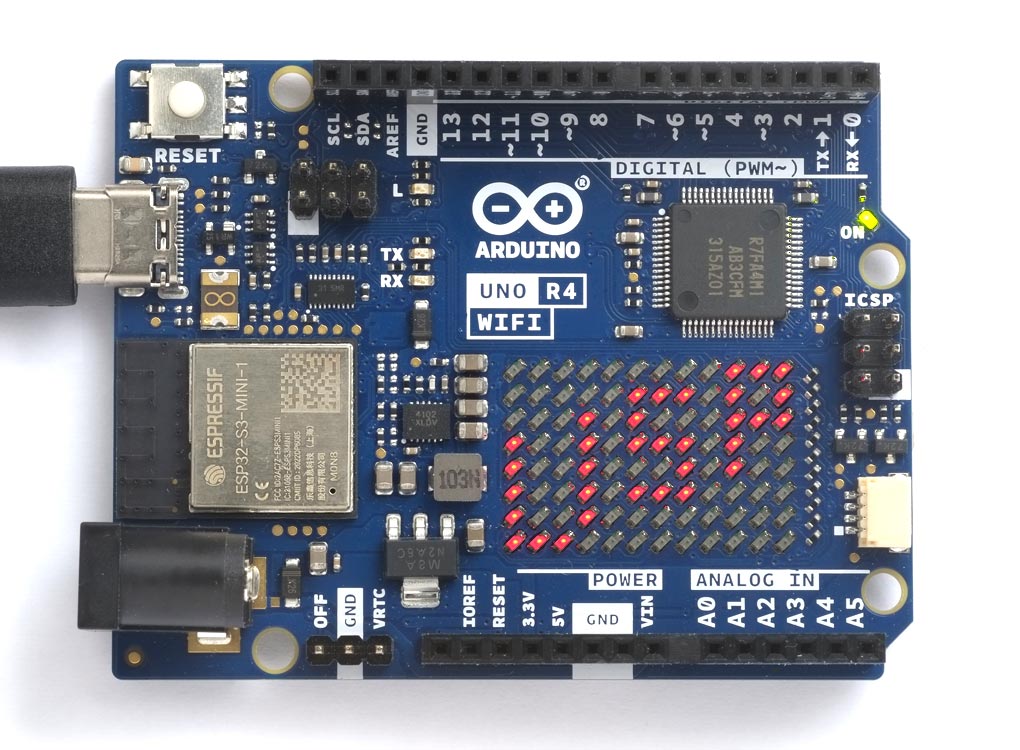
The Arduino Uno R4 boards are based on the Renesas RA4M1 ARM Cortex M4 CPU, with 256 KB flash memory, 32 KB RAM, and a 48 MHz clock.
The Arduino Uno R4 Minima [1], and its Wi-Fi version the Uno R4 WiFi [2], are being promoted as an easy step up from the original ATmega328P-based Arduino Uno, because they maintain the same form factor, shield compatibility, and 5 V operating voltage as their predecessor.
Unlike the other ARM-based boards, such as the Arduino Zero, all the I/O pins on the Arduino Uno R4 boards operate with 5 V logic, making them compatible with 5 V peripherals.
In addition to the features provided on the Uno R4 Minima, the Uno R4 WiFi incorporates an ESP32-S3 Wi-Fi board, supported by the uLisp Wi-Fi extensions, and an 8x12 LED matrix which you can control using a uLisp LED matrix extension.
Boards
Introduction
Saving the workspace
The Uno R4 boards provide 8192 bytes of emulated EEPROM, and uLisp uses this to allow you to save a workspace of up to 1024 objects using save-image. Note that on these boards it is very slow.
ARM assembler
The Uno R4 boards support the ARM assembler that allows you to generate machine-code functions, integrated with Lisp, written in ARM thumb code. The assembler itself is written in Lisp to make it easy to extend it or add new instructions. For more information see ARM assembler overview.
Installing uLisp from the Arduino IDE
Install the Arduino Renesas Boards core
- In the Arduino IDE search for the Arduino Renesas Boards core in Boards Manager and install it. I used version 1.2.2.
- Select Arduino Renesas UNO R4 Boards from the Board menu, and Arduino UNO R4 Minima or Arduino UNO R4 WiFi from the submenu.
You can leave all the other options at their defaults.
Upload uLisp
- Download the latest ARM version of uLisp from the Download uLisp page.
- Select the board's USB port from the Port menu
- Upload uLisp to the board.
Using uLisp
- You may need to select the board's USB port from the Port menu again.
- Select Serial Monitor from the Tools menu.
- Enter Lisp commands.
Putting the board into upload mode
If the upload fails you may need to put the board into upload mode first.
- Double-press the RESET button.
Arduino Uno R4 Minima
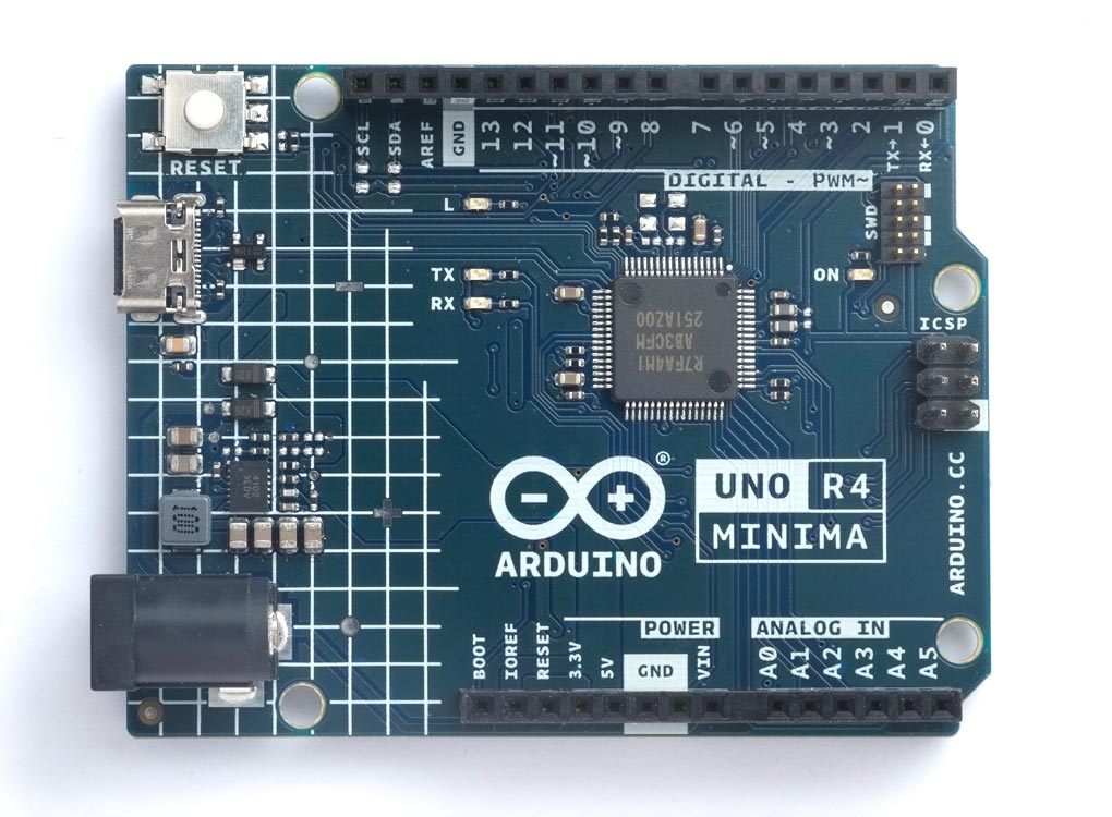
Pinout
LEDs
The Uno R4 Minima has an orange LED connected to the digital pin 13 which you can flash with the following program:
(defun blink (&optional x)
  (pinmode :led-builtin :output)
  (digitalwrite :led-builtin x)
  (delay 1000)
  (blink (not x)))
Run it by typing:
(blink)
Pin 13 can also be used as an analogue pin, so you can pulsate the orange LED slowly on and off with the program:
(defun pulse ()
  (let (down)
    (loop
     (dotimes (x 256)
       (delay 5)
       (analogwrite :led-builtin (if down (- 255 x) x)))
     (setq down (not down)))))
Run it by typing:
(pulse)
Exit from either program by entering ~.
Note that there's currently a problem in the Arduino R4 core that prevents digitalwrite from working correctly after analogwrite has been used on a pin; hopefully this will be fixed soon.
Digital inputs/outputs
The Uno R4 Minima provides 16 digital inputs/outputs, numbered 0 to 15. The maximum drive capability is 8mA on each pin.
The inputs/outputs can be defined as :input, :input-pullup, :output, and :output-opendrain.
Note: Pin 13 is defined as an output on reset.
Analogue inputs
The Uno R4 Minima has analogue inputs on pins 16 (A0) to 21 (A5).
Analogue reference
The Uno R4 Minima provides the following options for analogreference:
| Keyword | Description |
| :ar-default | Default reference of about 4.7 V |
| :ar-internal | Internal reference of about 1.4 V |
| :ar-external | Voltage applied to the AREF pin |
Analogue outputs
The Uno R4 Minima provides PWM outputs on pins 3, 5, 6, 9, 10, and 11. It also provides one 12-bit DAC output on pin 16 (A0).
Serial
The Uno R4 Minima provides one Serial port on pin numbers 0 (RX) and 1 (TX).
SPI
The Uno R4 Minima has one accessible SPI port on pin numbers 12 (MISO), 11 (MOSI), and 13 (SCK). It's also available on the ICSP connector.
I2C
The Uno R4 Minima provides one I2C ports on pin numbers 14 (SDA) and 15 (SCL).
Other features
Other features not yet supported by uLisp are as follows:
CAN Bus
The Uno R4 Minima provides a CAN Bus port on pin numbers 5 (RX) and 4 (TX).
Op Amp
The Uno R4 Minima provides a differential operational amplifier on the pins 15 (INPUT+), 16 (INPUT-), and 17 (OUTPUT).
Real-time clock
The Uno R4 Minima provides a real-time clock.
Arduino Uno R4 WiFi
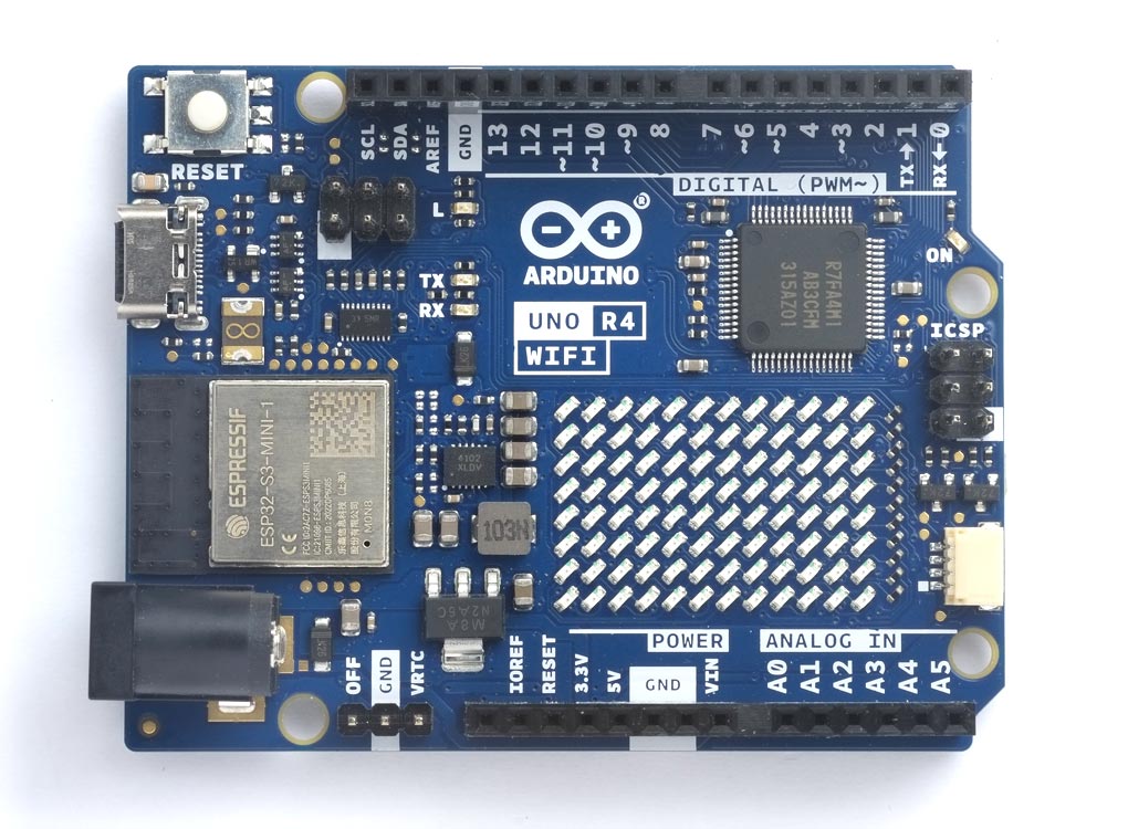
Pinout
Wi-Fi
The Uno R4 WiFi supports all the uLisp Wi-Fi extensions; see Wi-Fi extensions and Wi-Fi examples.
LEDs
The Uno R4 WiFi has an orange LED connected to the digital pin 13 which you can flash with the following program:
(defun blink (&optional x)
  (pinmode :led-builtin :output)
  (digitalwrite :led-builtin x)
  (delay 1000)
  (blink (not x)))
Run it by typing:
(blink)
Pin 13 can also be used as an analogue pin, so you can pulsate the orange LED slowly on and off with the program:
(defun pulse ()
  (let (down)
    (loop
     (dotimes (x 256)
       (delay 5)
       (analogwrite :led-builtin (if down (- 255 x) x)))
     (setq down (not down)))))
Run it by typing:
(pulse)
Exit from either program by entering ~.
Note that there's currently a problem in the Arduino R4 core that prevents digitalwrite from working correctly after analogwrite has been used on a pin; hopefully this will be fixed soon.
Digital inputs/outputs
The Uno R4 WiFi provides 16 digital inputs/outputs, numbered 0 to 15. The maximum drive capability is 8mA on each pin.
The inputs/outputs can be defined as :input, :input-pullup, :output, and :output-opendrain.
Note: Pin 13 is defined as an output on reset.
Analogue inputs
The Uno R4 WiFi has analogue inputs on pins 16 (A0) to 21 (A5).
Analogue reference
The Uno R4 WiFi provides the following options for analogreference:
| Keyword | Description |
| :ar-default | Default reference of about 4.7 V |
| :ar-internal | Internal reference of about 1.4 V |
| :ar-external | Voltage applied to the AREF pin |
Analogue outputs
The Uno R4 WiFi provides PWM outputs on pins 3, 5, 6, 9, 10, and 11. It also provides one 12-bit DAC output on pin 16 (A0).
Serial
The Uno R4 WiFi provides one Serial port on pin numbers 0 (RX) and 1 (TX).
SPI
The Uno R4 WiFi has one accessible SPI port on pin numbers 12 (MISO), 11 (MOSI), and 13 (SCK). It's also available on the ICSP connector.
I2C
The Uno R4 WiFi provides two I2C ports; port 0 on pin numbers 18 (SDA) and 19 (SCL), and port 1 on pin numbers 27 (SDA) and 26 (SCL). Port 1 is accessible on the Qwick/STEMMA QT connector at the right-hand edge of the board, but note that it is 3.3V only.
LED Matrix
The Uno R4 WiFi incorporates a charlieplexed 12x8 red LED matrix. To control the LED matrix from uLisp install the WiFi LED Matrix Extension as follows:
- Uncomment #define extensions at the start of the main uLisp source file.
- Compile and upload uLisp with the file LEDMatrix.ino included in the same folder as the uLisp source file for your platform.
The LED matrix functions will then be added to the built-in functions in uLisp.
Here is the LED matrix Extension: LEDMatrix.ino.
It includes the following functions:
matrix-begin
Syntax:(matrix-begin)
Initialises the LED matrix timer. You need to call this before using load-frame.
turn-led
Syntax:(turn-led led on)
Turns on or off a single led number, numbered 0 (top left) to 95 (bottom right).
load-frame
Syntax:(load-frame one two three)
Displays a static pattern of LEDs specified by the three 32-bit integer parameters.
For example:
(matrix-begin)
(load-frame #x3184a444 #x44042081 #x100a0040)
displays the Arduino heart.
The following function array-to-frame converts a two-dimensional uLisp array to a frame suitable for displaying on the LED matrix:
(defun array-to-frame (pic)
  (let ((x 0) (y 0) word result)
    (dotimes (words 3)
      (setq word 0)
      (dotimes (bits 32)
        (setq word (logior (ash word 1) (aref pic x y)))
        (incf y)
        (when (= y 12) (setq y 0) (incf x)))
      (push word result))
    (reverse result)))
It's quite easy to design an LED pattern in a text editor by creating an 8x12 array using defvar. For example:
(defvar *picture*
  #2a((0 0 0 0 0 0 0 0 0 1 1 1)
      (0 0 0 0 0 1 1 1 0 1 0 1)
      (0 0 0 1 0 1 0 0 0 1 1 1)
      (1 0 0 1 0 1 1 1 0 1 0 0)
      (1 0 0 1 0 0 0 1 0 1 0 0)
      (1 0 0 1 0 1 1 1 0 0 0 0)
      (1 0 0 1 0 0 0 0 0 0 0 0)
      (1 1 1 0 0 0 0 0 0 0 0 0)))
where '1' indicates an illuminated LED. You can then simply do:
(matrix-begin)
(apply load-frame (array-to-frame *picture*))
to display the LED matrix:
You could create an animated display by changing the contents of the array, and then calling load-frame again after a delay.
Other features
Other features not yet supported by uLisp are as follows:
CAN Bus
The Uno R4 WiFi provides a CAN Bus port on pin numbers 13 (RX) and 10 (TX).
Op Amp
The Uno R4 WiFi provides a differential operational amplifier on the pins 15 (INPUT+), 16 (INPUT-), and 17 (OUTPUT).
Real-time clock
The Uno R4 WiFi includes a real-time clock, and additional pins, including an OFF pin to turn off the board and a VRTC pin to keep the real-time clock powered and running.
- ^ Arduino UNO R4 Minima on Arduino.cc.
- ^ Arduino UNO R4 WiFi on Arduino.cc.