Maxim MAX32620FTHR
The Maxim MAX32620FTHR board is an Feather-style board based on the MAX32620 96 MHz ARM Cortex M4F microcontroller:
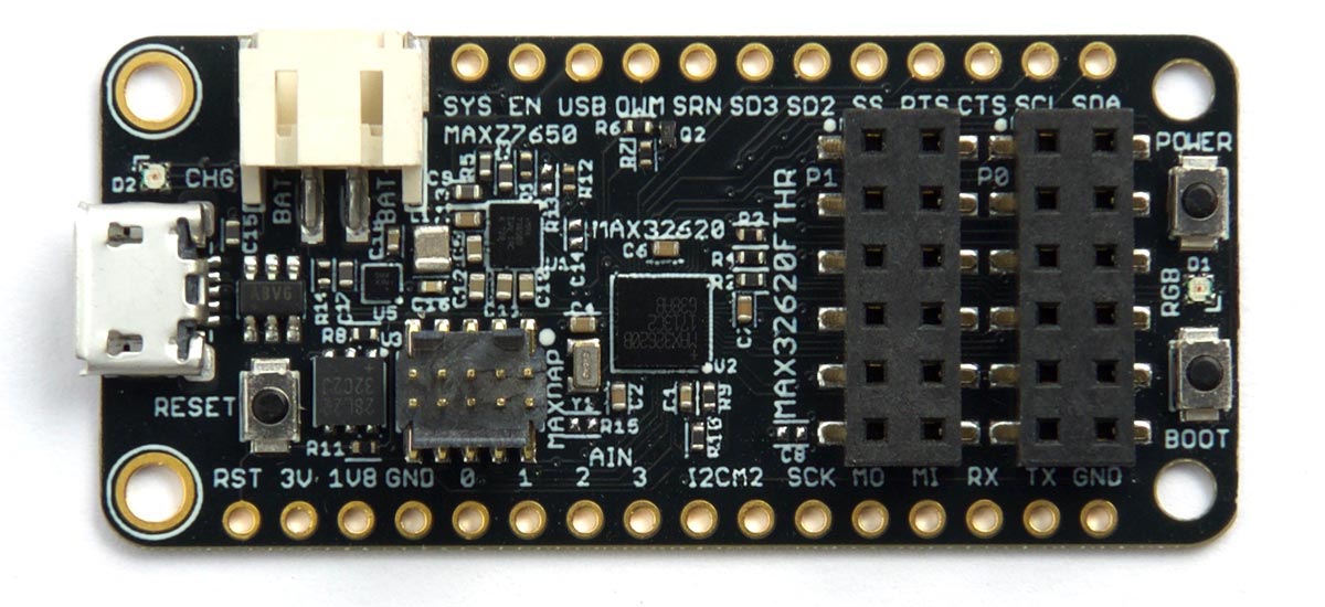
The board provides 2048 KB flash and a generous 256 KB RAM. It includes a JST socket for a Lipo battery, and provides several features ideal for battery-operated applications: a MAX77650 SIMO Buck-Boost PMIC for power conversion and battery management, and a MAX17055 Fuel Gauge to measure battery life [1].
Uploading uLisp from the Arduino IDE
- Install the Arduino Core as described on Maxim's GitHub page [2].
- On the Boards menu, under the heading Maxim-ARM (32 bits) Boards select MAX32620FTHR(Native USB port).
- Connect the board to the computer via USB.
- Press and hold the Boot button on the board.
- Press and release the Reset button.
- After the red LED turns on release the Boot button.
- Upload the ARM version of uLisp.
Ignore all the warnings from the core concerned with redefining true and false.
Details of the board are given in the MAX32620FTHR Wiki: MAX32620FTHR.
RGB LED
The MAX32620FTHR board has an RGB LED connected to pins 20 (red), 21 (green), and 22 (blue). For example, you can make it blue by evaluating:
(digitalwrite 22 0)
The following program cycles all three LEDs through the 8 different combinations of colours:
(defun rgb ()
  (let ((leds '(20 21 22)))
    (mapc (lambda (p) (pinmode p t)) leds)
    (loop
     (dotimes (x 8)
       (mapc (lambda (p) (digitalwrite p (logand x 1)) (setq x (ash x -1))) leds)
       (delay 1000)))))
Run it by typing:
(rgb)
Exit from the program by entering ~.
All the I/O pins can also be used with analogwrite, so you can make the LED faint blue with:
(analogwrite 22 240)
For an analogue version of the above rgb program that you can run on the MAX32620FTHR board see Mood light.
Analogue inputs
The MAX32620FTHR board has four analogue inputs on pins 49 (A0) to 52 (A3). The resolution is 10 bits.
Analogue outputs
The MAX32620FTHR board can do analogue output on any pin.
Serial
There are three serial ports, one of which is accessible through the Arduino IDE Serial Monitor.
SPI
There are three SPI ports, although only SPI2 is accessible from the Arduino core and hence uLisp.
I2C ports
The MAX32620FTHR board provides three I2C ports, although only two are accessible from uLisp.
The external I2C port is on pins 28 (SDA) and 29 (SCL). The internal I2C devices are on I2C port 2, on pins 47 (SDA) and 48 (SCL) but these are translated to port 1 in uLisp. To access these give the with-i2c command with port 1 as a second parameter. For example, to scan port 1 give:
(defun scn ()
  (dotimes (p 127)
    (with-i2c (str 1 p)
(when str (print p)))))- ^ MAX32620FTHR on GitHub.
- ^ Arduino Core for Maxim's MAX326xx series boards on GitHub.