A LoRaWAN node using uLisp
LoRa is a low-power wireless protocol ideal for collecting data from sensors and other small devices. They typically communicate wirelessly with a LoRaWAN Gateway, with a range of about 2 km, which then transfers the data to the internet so it can be collected for analysis and display.
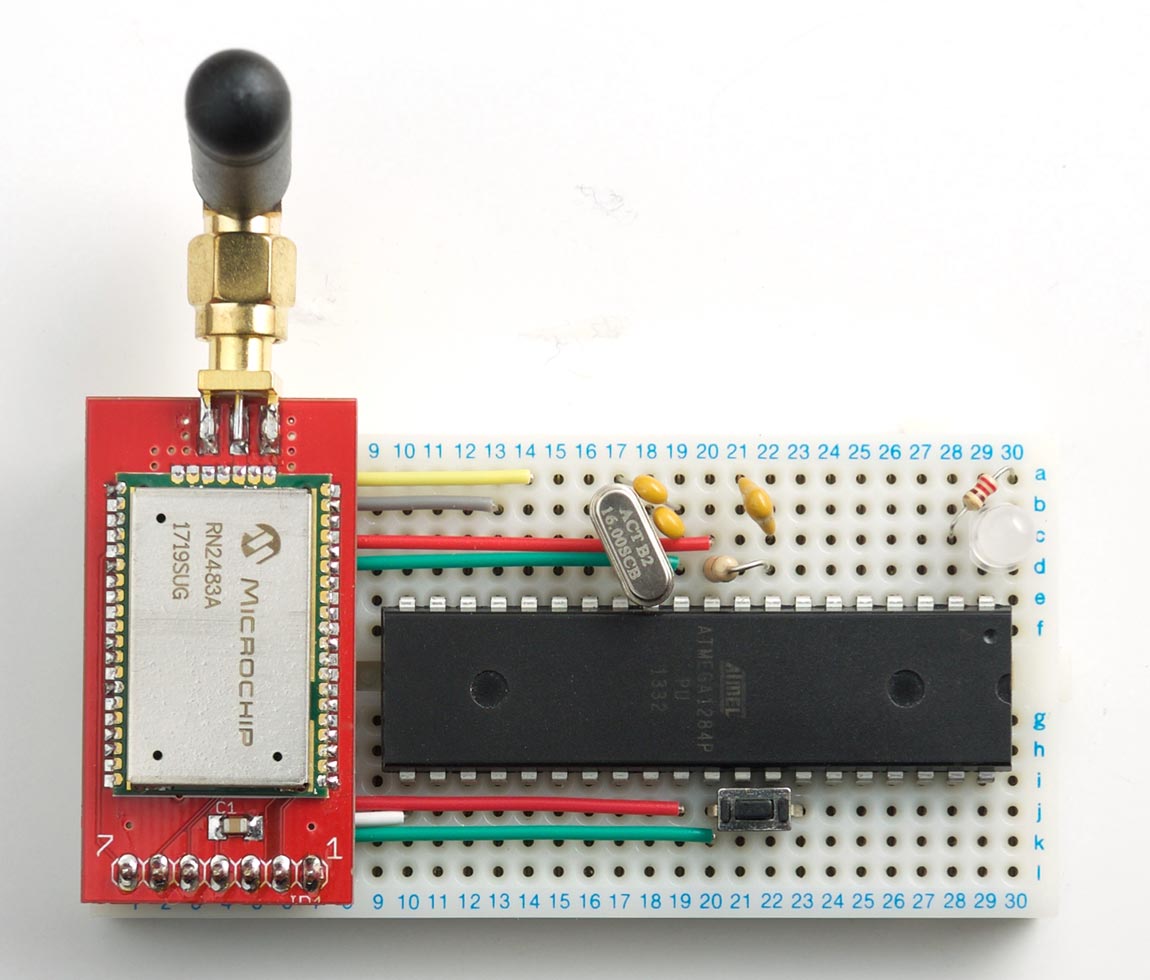
This post describes a LoRaWAN node, based on a Microchip RN2483A interfaced to an ATmega1284, and controlled by a program written in uLisp, the small Lisp interpreter for the Arduino:
The full uLisp LoRaWAN Node program is described in the following sections. Once you've installed the uLisp program you can save it in EEPROM and make it run automatically on reset, using the uLisp save-image command. You can then disconnect the FTDI board and use the circuit as a stand-alone LoRaWAN node.
What is LoRaWAN?
LoRaWAN is a wireless communication protocol that operates in the unlicensed spectrum, with a range of around 1km to 10km, depending on the environment. A typical setup consists of a gateway, that listens for transmissions from nodes within range, and a set of nodes that transmit data. It is designed for very low data rates, of a few bytes every few minutes, and so is ideal for applications such as environmental measurements, metering, and healthcare monitoring.
The Things Network
A community-led project called The Things Network (TTN) is setting up a global network of LoRaWAN Gateways, linked via a free access website [1]. If there's already a TTN gateway near you [2], you can transmit data to it from a LoRa Node, and then collect it via the Internet for display or analysis. If there isn't a TTN gateway near you, you could contribute to the Things Network by buying a gateway and installing it; the Things Network launched a gateway on Kickstarter which is expected to be generally available at the end of 2017 [3], or you could build one based on a Raspberry Pi. For more information see The Things Network Forum.
Building a LoRa node based on an ATmega1284
A simple way to build a LoRa node is to base it on the Microchip RN2483A, a module that does much of the work of handling the LoRaWAN protocols; you interface to it using a standard 57600-baud serial link, using a series of text commands [4].
The following example shows how to drive a Microchip RN2483A from uLisp, allowing you to set it up interactively from the Arduino IDE's Serial Monitor. The advantage of using uLisp over C or C++ is that it's more concise, so you can clearly see the sequence of commands. Also, because uLisp is an interpreter you can interact with the uLisp program from the Serial Monitor, without needing to recompile and upload the source each time, so it's easy to make small changes and rerun the program to test alternative settings.
Mounting the RN2483A on a breakout board
I mounted the RN2483A on a breakout board to make it easier to put on the prototyping board, and attach an aerial. I tried two different breakout boards: one designed by Andrew Lindsay of Thing Innovations [5], available to order from DirtyPCBs [6], and one designed by Spence Konde (Dr. Azzy) and available from his Tindie store [7]. I chose the first one for this project, as it's slightly smaller. Note that it is surprisingly difficult to solder the RN2483 to the breakout board, even if you've done some SMD soldering before, because the LoRaWAN module acts as a heatsink, making it hard to melt the solder evenly on the pads.
The circuit
Here's the circuit for the LoRaWAN Node:
I built the circuit on a small 30x12 hole prototyping board, which was just wide enough to fit the RN2483 module and ATmega1284 processor.
For the indicator light I used a Red/Green bicolour LED [8], but you could equally well use two separate LEDs. I powered the whole circuit from a 3.7V Lipo battery.
Programming the LoRaWAN Node
To program the ATmega1284 in uLisp you first need to install a bootloader, so the processor can be programmed via the serial interface, and then install uLisp.
Installing a bootloader
Unless you've bought an ATmega1284 chip with a bootloader already installed, the first step is to upload a bootloader using In-System Programming (ISP). One way is to use an Arduino Uno as an ISP programmer [9]:
- Remove the RN2483 breakout from the breadboard, as this is only rated at 3.3V.
- Connect the Arduino Uno to the ATmega1284P on the breadboard as follows:
| Arduino Uno | ATmega1284 |
| pin 10 | pin 9 (RST) |
| pin 11 | pin 6 (PB5, MOSI) |
| pin 12 | pin 7 (PB6, MISO) |
| pin 13 | pin 8 (PB7, SCK) |
| GND | GND (pin 11) |
| Vcc | Vcc (pin 10) |
Now download Jack Christensen's Mighty 1284P core [10]. and proceed as follows:
- Install the Mighty 1284P core.
- On the Tools -> Board submenu choose "maniacbug" Mighty 1284p 16MHz using Optiboot.
- Select the sketch File -> Examples -> 11.ArduinoISP -> ArduinoISP and upload it to the Arduino Uno.
- Select Tools -> Programmer -> Arduino as ISP.
- Select Tools -> Burn Bootloader.
Installing uLisp
Once you've installed a bootloader you can upload programs via an FTDI USB-to-serial converter on an external board, connected as shown in the above circuit. There are several alternatives available; I used the FTDI Basic Breakout from Sparkfun [11], available from HobbyTronics in the UK [12].
Note that you should set the voltage link on the back of the FDTI board to 3.3V, as the RN2483 is only rated for 3.3V.
Use this to upload the latest version of uLisp for the Arduino from the Download and install uLisp page.
Programming in uLisp
You should now be able to run uLisp and get the uLisp prompt in the Serial Monitor; see Using uLisp. You can test that everything's working by entering the following program, that will flash the bi-colour LED green and red:
(defun blink (x)
  (pinmode 0 t)
  (pinmode 1 t)
  (digitalwrite 0 x)
  (digitalwrite 1 (not x))
  (delay 1000)
  (blink (not x)))
Run it by typing:
(blink t)
Escape from the program by typing a "~" in the Serial Monitor.
Communicating with the RN2483
To register the node on The Things Network we will need the unique device ID of the RN2483 module. The fisrt step is to write a uLisp program to communicate with the RN2483 via the serial port.
First define a constant resetpin for the ATmega1284 pin used to reset the RN2483:
(defvar resetpin 15)
Next define a function reset that resets the RN2483:
(defun reset ()
  (pinmode resetpin t)
  (digitalwrite resetpin nil)
  (delay 500)
  (digitalwrite resetpin t)
  (delay 100))
Next we write a function write-crlf that writes a string str to an output stream stream, terminated by CR/LF, echoes it to the Serial Monitor, and then reads back the response from the stream and echoes that to the Serial Monitor:
(defun write-crlf (str stream)
  (let ((line (concatenate 'string str (string #\return))))
    (write-line line stream)
    (print line)
    (print (read-line stream))))
Finally, here's the routine to read the Device EUI, called hweui in the RN2483:
(defun deveui ()
  (with-serial (lora 1 576)
    (let ((command (lambda (s) (write-crlf s lora)))
          (count 10)
           hweui)
      ;
      ; Reset RN2483
      (reset)
      ;
      ; Read welcome message
      (print (read-line lora))
      (delay 1000)
      (command "mac reset 868")
      ;
      ; Get deveui from RN2483
      (setq hweui (command "sys get hweui")))))
Run this by typing:
(deveui)
You should get output similar to the following:
"RN2483 1.0.3 Mar 22 2017 06:00:42"
"mac reset 868"
"ok"
"sys get hweui"
"1234A30B001FCBE1"
"1234A30B001FCBE1"
Registering your application
The Things Network allows you to set up an application, and then assign one or more devices ie nodes to that application. For example, your application could be monitoring the temperature of your greenhouses, and the nodes would transmit the temperature from each greenhouse.
- Sign up for a free account on The Things Network.
- Display the Console by linking to:
https://console.thethingsnetwork.org/
- Click the Applications icon.
- Click the add application link.
The ADD APPLICATION page is displayed.
- Enter an ID for the application in the Application ID field.
For example, this could be greenhousemonitor.
- Optionally add a description in the Description field.
- Click the Add application button.
The Things Network will generate an Application EUI for the application and display it in the APPLICATION OVERVIEW page; for example:
70B3D57ED1237850
Adding a device
The next step is to add a device, or node, to the application.
- Click the Devices tab, and click the register device link.
- Enter an ID for the device in the Device ID field.
For example, this could be sensor1.
- Enter the Device EUI read from the RN2483 in the previous section in the Device EUI field.
- Click the Register button.
The Things Network will generate an App Key for the device, and you can copy it from the App Key field on the DEVICE OVERVIEW page.
Join the TTN network
Having obtained an Application EUI for our greenhousemonitor application, and an App Key for the first node, sensor1, we are now in a position to activate the node on The Things Network.
First define two more constants for the two keys and the pin used for the button:
(defvar appeui "70B3D57ED1237850")
(defvar appkey "12323A30FF3430E380F2428D723DFA8B")
(defvar button 30)
Here's a routine status that controls the status light:
(defun status (n)
  (pinmode 0 t) (pinmode 1 t)
  (digitalwrite 0 nil) (digitalwrite 1 nil)
  (cond
   ((= n 1) (digitalwrite 0 t))
   ((= n 2) (digitalwrite 1 t))))
The parameter 0=off, 1=green, and 2=red.
Finally, here's the whole routine to set up the RN2483, join The Things Network, and then send test data every time the button is pressed:
(defun run ()
  (status 0)
  (with-serial (lora 1 576)
    (let ((command (lambda (s) (write-crlf s lora)))
          (count 10)
           hweui)
      (pinmode button 2)
      ;
      ; Reset RN2483
      (reset)
      ;
      ; Read welcome message
      (print (read-line lora))
      (delay 1000)
      (command "mac reset 868")
      ;
      ; Get deveui from RN2483
      (setq hweui (command "sys get hweui"))
      (setq hweui (subseq hweui 0 16))
      (command (concatenate 'string "mac set deveui " hweui))
      ;
      ; Join TTN using OTAA
      (command (concatenate 'string "mac set appeui " appeui))
      (command (concatenate 'string "mac set appkey " appkey))
      (command "mac set pwridx 1")
      (command "mac set adr off")
      (command "mac set ar off")
      (command "mac join otaa")
      (let ((response (print (read-line lora))))
        (cond
         ((not (string= (subseq response 0 6) "accept"))
          (status 2))
         (t
          (status 1)
          (loop
           (when (null (digitalread button))
             (status 0)
             (command (concatenate 'string
                                   "mac tx uncnf 1 "
                                   (princ-to-string (incf count))))
             (let ((response (print (read-line lora))))
               (cond
                ((string= (subseq response 0 6) "mac_tx")
                 (status 1))
                (t (status 2))))))))))))
To run this routine type:
(run)
After a delay of about 10 seconds the status light should turn green if Over-The Air Activation (OTAA) was successful, or red if it failed if, for example, you hadn't registered the device, or if you are not in range of a gateway.
Pressing the button then transmits a byte "11" to the gateway; again, the status light is green if the byte was transmitted successfully, or red if it failed. Each time you press the button the value of the byte is incremented. You will be able to see the data on your application page in The Things Network Console.
It would be quite simple to modify the program to instead send regular temperature measurements, by interfacing the ATmega1284 to a suitable temperature sensor; for example, see Temperature sensor.
Making the uLisp program run automatically
Once you're satisfied that the uLisp program is working correctly you can save it to EEPROM, and then set up the ATmega1284 so the program runs automatically on reset, without needing the FTDI interface to be connected:
- Uncomment the following line in the uLisp source :
#define resetautorun
- Upload uLisp to the ATmega1284 again.
- Enter the uLisp programs, and save them to EEPROM with the command:
(save-image 'run)
The second parameter specifies that the routine (run) should be run automatically on reset.
For questions about this application, or to suggest improvements or extensions, please post on the uLisp Forum.
- ^ See The Things Network manifesto
- ^ See Communities on The Things Network.
- ^ The Things Gateway on The Things Network website.
- ^ RN2483 Command Reference on the Microchip web site.
- ^ Getting started with Microchip RN2483 LoRaWAN modules on Thing Innovations.
- ^ RN2483 breakout on DirtyPCBs.
- ^ RN2483 breakout (bare board) on Tindie.
- ^ Kingbright L-57EGW 568/625 nm Bi-color Green & Red LED on RS-Online.
- ^ Using an Arduino as an AVR ISP on Arduino.cc.
- ^ Mighty 1284P core on Github.
- ^ FTDI Basic Breakout on Sparkfun.
- ^ FTDI Basic Breakout on HobbyTronics.