LILYGO T-Display RP2040
The LILYGO T-Display RP2040 [1] is an RP2040-based board with a built-in 240x135 colour TFT display which you can plot to using the uLisp graphics extensions:
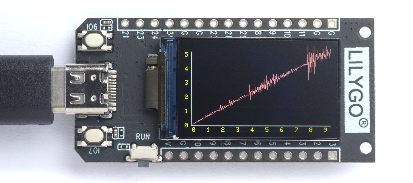
It includes two user buttons, an LED, a mini socket for powering the board from a LiPo cell (not compatible with Adafruit LiPo cells, but a cable is provided), and battery voltage detection. You can charge the LiPo cell from the USB port.
It's the same display as used on the Adafruit ESP32-S2 TFT Feather and TTGO T-Display.
The plot shown above is drawn using the following program: Plotting the Hofstadter Q sequence.
Installing uLisp from the Arduino IDE
Install the Raspberry Pi Pico/RP2040 core
- Add the following URL to the Additional Boards Manager URLs list in the Arduino IDE Preferences dialog box:
https://github.com/earlephilhower/arduino-pico/releases/download/global/package_rp2040_index.json
- In the Arduino IDE search for the Raspberry Pi Pico/RP2040 core in Boards Manager and install it.
I tested this with core version 4.5.0 which uses the new certified 200 Mhz clock.
- Select Raspberry Pi RP2040 Boards from the Board menu, and Raspberry Pi Pico from the submenu.
- Set Flash Size to 2MB (Sketch: 1MB, FS: 1MB).
This allocates enough space for use by LittleFS to save the entire workspace with save-image.
You can leave all the other options at their defaults.
Upload uLisp
- Download Release 4.4c or later of the ARM version of uLisp from the Download uLisp page.
- Enable the uLisp graphics support by uncommenting the line:
#define gfxsupport
- Select the board's USB port from the Port menu
- Upload uLisp to the board.
Using uLisp
- You may need to select the board's USB port from the Port menu again.
- Select Serial Monitor from the Tools menu.
- Enter Lisp commands.
Putting the board into upload mode
If the upload fails you may need to put the board into upload mode first.
On boards with a reset button, such as the Adafruit boards:
- Press and hold the BOOT button on the reverse of the board.
- Press the RUN (reset) button.
- Release the Boot button.
Pins
For more information about the board see the LILYGO T-Display GitHub page [2].
LEDs
The LILYGO T-Display RP2040 has an RGB LED connected on pin 17 (red), and a blue/green LED on pins 16 (green) and 25 (blue). Note that the LEDs are turned on with nil (or 0), and off with t (or 1).
You can flash the red LED with the following program:
(defun blink (&optional x)
  (pinmode :led-builtin :output)
  (digitalwrite :led-builtin x)
  (delay 1000)
  (blink (not x)))
Run it by typing:
(blink)
Buttons
The LILYGO T-Display RP2040 has two buttons on pins 6 and 7.
Analogue inputs
The LILYGO T-Display RP2040 has 4 analogue inputs which you can access on pins 26 (A0) to 29 (A3). They have up to 12-bit precision.
Analogue input 26 is connected to VBAT, the battery voltage, via a potential divider consisting of two 1MΩ resistors, so the voltage is given by:
(* (/ (analogread 26) 1024) 3.3 2)
With the USB connected this will give the charging voltage, typically 4.4V.
Analogue outputs
You can generate an analogue output using PWM on any of the digital pins. The precision is 8 bits.
Serial
The LILYGO T-Display RP2040 has one serial port on pin numbers 1 (RX) and 0 (TX). By default the baud rate is 9600.
SPI
The LILYGO T-Display RP2040 has one SPI port on pin numbers 4 (MISO), 3 (MOSI), and 2 (SCK).
I2C
The LILYGO T-Display RP2040 has one I2C port on pin numbers 6 (SDA) and 7 (SCL).
- ^ T-Display RP2040 on lilygo.cc.
- ^ LILYGO T-Display RP2040 on GitHub.