Seeed Studio Wio Terminal
The Seeed Wio Terminal [1] is based on the ATSAMD51P19 ARM Cortex M4 microcontroller running at 120 MHz, with 512 KB flash and 192 KB RAM. It also includes a 4 MB DataFlash chip, which uLisp uses to allow you to save the workspace, and a Realtek RTL8720DN providing Wi‑Fi and Bluetooth. It is equipped with a 2.4” 320x240 colour TFT display, an LIS3DHTR accelerometer, a microphone, buzzer, microSD card slot, light sensor, and infrared emitter (IR 940nm). It also has two multifunction Grove ports:
It's housed in an attractive compact case, about 72 mm x 56 mm, and a matching battery chassis is available [2] with additional Grove interfaces. For more information about the Wio Terminal see Getting Started with Wio Terminal on the Seeed Wiki.
The Wio Terminal is fitted with a USB-C socket, but it is supplied with a USB-C to Type A USB 3.0 cable so you can use it with computers that have older USB sockets.
Installing uLisp from the Arduino IDE
Install the Seeed SAMD Boards core
- Add the following URL to the Additional Boards Manager URLs list in the Arduino IDE Preferences dialog box:
https://files.seeedstudio.com/arduino/package_seeeduino_boards_index.json
- In the Arduino IDE search for the Seeed SAMD Boards core in Boards Manager and install it.
- Select Seeed SAMD (32-bits ARM Cortex-M0+ and Cortex-M4) Boards from the Board menu, and Seeeduino Wio Terminal from the submenu.
You can leave all the other options at their defaults.
Upload uLisp
- Download the latest ARM version of uLisp from the Download uLisp page.
- To use the graphics extensions uncomment the compile option:
#define gfxsupport
- Upload uLisp to the board.
You should then be able to select the USB port from the Port menu, select Serial Monitor from the Tools menu, and enter Lisp commands.
Putting the board into upload mode
If the upload fails you may need to put the board into upload mode first.
- Slide the on/reset button on the side of the Wio Terminal down, and release it.
You should be able to see the green LED illuminated through the plastic window.
Pin connections
The Wio Terminal has a 40-pin 0.1" pitch connector on the back which gives access to the pin connections:
Grove connectors
The Wio Terminal provides two Grove connectors for connecting external sensors. For details of the connections see: Wio Terminal IO Overview on GitHub.
SD card
The Wio Terminal provides an SD card socket, allowing you to use an SD card for file storage and for saving/loading Lisp images from uLisp.
To use the SD card compile uLisp with the #define sdcardsupport option enabled.
Analogue inputs
The Wio Terminal has 9 analogue inputs on pins 0 (A0) to 8 (A8).
Analogue outputs
The Wio Terminal has PWM analogue outputs on pins 0 to 2, 6, 8, 12 to 20, and 24.
Buzzer
The Wio Terminal has a buzzer on Arduino pin 12.
For example, the following function scale plays the scale of C:
(defun scale ()
  (mapc
   (lambda (n) (note 12 n 4) (delay 500))
   '(0 2 4 5 7 9 11 12))
  (note))
Serial
The PyGamer and PyBadge have a serial port on pin numbers 1 (TX) and 0 (RX).
SPI
The Wio Terminal has four SPI interfaces. SPI1, SPI2, and SPI3 are used for the RTL8720D, SD card, and TFT display respectively. There's also a QSPI interface used by the DataFlash chip.
I2C
The Wio Terminal has two I2C ports. Port 0 is the I2C Grove port, and port 1 is the LIS3DH accelerometer.
Wi‑Fi and Bluetooth
Access to the RTL8720D for Wi-Fi and Bluetooth isn't yet supported in uLisp.
TFT Graphics Display
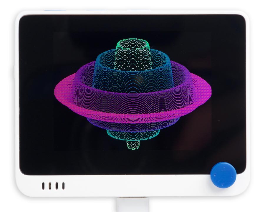
The Wio Terminal includes a 320x240 colour graphics display which is supported by the uLisp graphics extensions. For details see Graphics extensions.
The photograph above shows the Surface of rotation example, plotted with:
(defun sinfun (r) (* (- r 1) (sin (* r 24))))
(rotation 320 240 sinfun)
It defines the plot area as being 318x240 because the bezel masks the rightmost column of pixels on the display.
Push buttons and joystick
The Wio Terminal has three user buttons above the screen:
| Pin | Button |
| 28 | BUTTON 1 (rightmost) |
| 29 | BUTTON 2 (centre) |
| 30 | BUTTON 3 (leftmost) |
In addition the Wio Terminal has a digital joystick connected to the following pins:
| Pin | Action |
| 31 | UP |
| 32 | LEFT |
| 33 | RIGHT |
| 34 | DOWN |
| 35 | PRESS |
The pins should be configured as :input-pullup, and they are low when pressed.
Etch-a-sketch demo
Here's a simple etch-a-sketch program that lets you draw with the joystick:
(defun etchasketch ()
  (fill-screen)
  (let ((x0 160) (y0 120))
    (dotimes (p 5) (pinmode (+ p 31) 2))
    (loop
     (let* ((y (+ y0 (if (digitalread 34) 0 1) (if (digitalread 31) 0 -1)))
            (x (+ x0 (if (digitalread 33) 0 1) (if (digitalread 32) 0 -1))))
       (draw-line x0 y0 x y)
       (setq x0 x y0 y)
       (delay 10)))))
Accelerometer
The Wio Terminal includes an LIS3DH low power triple-axis accelerometer with 10-bit precision. It is connected to the Wire1 I2C interface, and has the address 0x18, or 24.
The sensor provides a number of different operating modes for different applications, and a FIFO allowing you to buffer 32 10-bit readings. The following routines run the sensor in the default Normal Mode, which provides 10-bit accuracy, and FIFO Bypass mode, which ignores the FIFO.
Setting the sample rate
By default the sensor is in low-power mode, so to take readings you need to set the rate. The following routine lis3dh-rate takes a parameter from 0 to 9:
(defun lis3dh-rate (x)
  (with-i2c (s 1 #x18)
    (write-byte #x20 s)
    (write-byte (logior (ash x 4) 7) s)))
For example to set a 10Hz sample rate:
(lis3dh-rate 2)
Reading the accelerometer
The following routine s16 returns a signed 16-bit integer from two bytes, LSB first:
(defun s16 (s)
  (let ((d (logior (read-byte s) (ash (read-byte s) 8))))
    (- d (ash (logand d #x8000) 1))))
The following routine lis3dh-xyz then returns the acceleration data as a list of three signed integers:
(defun lis3dh-xyz ()
  (with-i2c (s 1 #x18)
    (write-byte (+ #x28 #x80) s) ; Set top bit to read multiple bytes
    (restart-i2c s 6)
    (let (dat)
      (dotimes (i 3) (push (s16 s) dat))
      (reverse dat))))
At the default full-scale sensitivity, 2g, a value of 32767 represents 2g and -32768 represents -2g.
For example:
> (lis3dh-xyz)
(-320 192 -15232)
If the sensor is stationary the x and y figures will be close to zero, and the z value will be close to -16384, corresponding to 1g (since the sensor is mounted on the bottom of the board).
Floating-point version
The following routine will return the values in g, based on the currently selected full-scale sensitivity:
(defun lis3dh-g3d ()
  (let ((fs (with-i2c (s 1 #x18)
              (write-byte #x23 s)
              (restart-i2c s 1)
              (logand 3 (ash (read-byte s) -4)))))
    (mapcar (lambda (i) (/ i (ash 16384 (- fs)))) (lis3dh-xyz))))
For example:
> (lis3dh-g3d)
(-0.015625 0.015625 -0.949219)
Setting the sensitivity
The following routine set sets the full-scale sensitivity of the accelerometer:
(defun lis3dh-set (x)
  (with-i2c (s 1 #x18)
    (write-byte #x23 s)
    (write-byte (ash x 4) s)))
The parameter can be 0 for ±2g, 1 for ±4g, 2 for ±8g, or 3 for ±16g.
Rolling ball demo
Here's a demonstration of using the accelerometer to display a ball on the screen which rolls around when you tilt the Wio Terminal. It uses the functions lis3dh-rate, lis3dh-xyz, and s16 given above:
(defun signum (x)
  (cond ((< x 0) -1) ((> x 0) +1) (t 0)))

(defun ball ()
  (lis3dh-rate 2)
  (fill-screen)
  (let ((x 160)
        (y 120)
        (r 4)
        (sens 1024)
        dx dy x1 y1)
    (fill-circle x y 4 -1)
    (loop
     (fill-circle x y 4 0)
     (let ((xyz (lis3dh-xyz)))
       (setq x (mod (- x (signum (truncate (second xyz) sens))) 320))
       (setq y (mod (+ y (signum (truncate (first xyz) sens))) 240))
       (fill-circle x y 4 -1))
     (delay 5))))
To run it, evaluate:
(ball)
- ^ Wio Terminal on Seeed Studio.
- ^ Wio Terminal Battery Chassis on Seeed Studio.