AVR DA and DB series boards
The Microchip DA and DB series parts run at up to 24 MHz and have up to 128 Kbytes of flash and 16 Kbytes of RAM. They include a DAC and 12-bit analogue inputs, in addition to the new features introduced with the ATmega 0-series such as the Event System and Configurable Custom Logic.
In addition, the DB-series parts feature:
- Eight I/O pins with Multi-Voltage I/O (MVIO), allowing them to operate at a different voltage from the positive supply.
- Analogue OPAMP peripheral with three op amps that can be used as amplifiers, unity gain buffers, programmable gain amplifiers (PGAs), or instrumentation amplifiers.
The naming of the new parts follows a new scheme, which is more logical than the earlier AVR naming conventions. Each device is named AVRmmmDApp or AVRmmmDBpp, where mmm is the amount of flash, and pp is the number of pins.
Microchip has made Curiosity Nano evaluation boards available for the AVR128DA48 and AVR128DB48, both based on the 48-pin chip with the largest amount of flash memory, and uLisp now supports both of these.
As of Version 3.6 uLisp includes an AVR assembler that allows you to generate machine-code functions, integrated with Lisp, written in AVR code. The assembler itself is written in Lisp to make it easy to extend it or add new instructions.
Update
16th June 2024: Added a note to report a problem with DxCore 1.5.8 or later.
Boards
Common features
Installing uLisp from the Arduino IDE
Note: You need to use DxCore 1.5.6 as there's a problem with resassigning Serial on later versions.
- First download the latest AVR version of uLisp from the Download uLisp page.
- Install Spence Konde's DxCore version 1.5.6, as described in DxCore – Installation.
- Connect the Curiosity Nano to the computer with a USB cable.
- On the Board menu, under the heading DxCore select AVR DA-series (no bootloader) or AVR DB-series (no bootloader) as appropriate.
- Check that the subsequent options are set as follows (ignore any other options):
Chip: "AVR128DA48" or "AVR128DB48"
Clock Speed: "24MHz internal"
Write to flash from app: "Above 96K (AVR128 only)"
- Select the port corresponding to the Curiosity Nano board from the Port menu.
- Set Programmer to Curiosity Nano (nEDBG, debug chip: ATSAMD21E18).
- Click Upload.
You should then be able to select Serial Monitor from the Tools menu, and enter Lisp commands.
Changing the target voltage
By default the voltage on the Curiosity Nano AVR128DA48 and AVR128DB48 boards is 3.3V, but they allow you to set the target voltage to either 3.3V or 5.0V. Once set the change will remain in effect even when the board is powered down.
To change the voltage simply create a text file and copy it to the board's mass storage disk. The filename or extension is irrelevant; the content should be one of the following:
| Text | Effect |
| CMD:1V8 | Sets the target voltage to 1.8V (DB board only) |
| CMD:3V3 | Sets the target voltage to 3.3V |
| CMD:5V0 | Sets the target voltage to 5.0V |
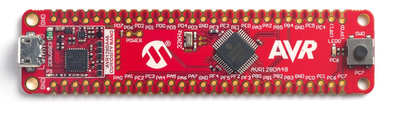
AVR128DA48 Curiosity Nano
Microchip's AVR128DA48 Curiosity Nano evaluation board [1] makes a very low-cost platform for running uLisp.
The board includes a debugger, providing a USB-to-serial interface, which is connected to Serial1:
It's available from suppliers such as Farnell [2].
LED
The Curiosity Nano has a yellow LED connected to pin 20 which you can flash with the following program:
(defun blink (&optional x)
  (pinmode 20 :output)
  (digitalwrite 20 x)
  (delay 1000)
  (blink (not x)))
Run it by typing:
(blink)
Exit from the program by entering ~.
You can save the blink program to EEPROM by typing the command:
(save-image)
You can now load it again after a reset by typing:
(load-image)
AVR Version 3.5b of uLisp now uses the flash memory for save-image, allowing you to save the entire workspace.
Button
The Curiosity Nano has a user button connected between pin 21 and GND which you can test with the following program:
(defun test ()
  (pinmode 21 :input-pullup)
  (loop
   (print (digitalread 21))
   (delay 1000)))
Analogue inputs
The AVR DA series chips support 12-bit analogue readings with analogread. By default they are 10-bit for compatibility with other Arduino boards, but you can select 12-bit with:
(analogreadresolution 12)
The analogue reference voltage can be selected with analogreference. For example:
(analogreference :internal2v048)
The options are :vdd or :default, :internal1v024, :internal2v048, :internal4v096, :internal2v5, or :external.
In addition to specifying a pin number to analogread you can also specify one of the following keywords:
- :adc-dac0 reads the value being output by DAC0.
- :adc-temperature reads the internal temperature sensor.
Analogue outputs
The Curiosity Nano can generate an analogue output using PWM on any of the digital pins 4, 5, 8 to 19, 38, or 39.
Note
You can use the note function with Arduino pins 38 and 39, which are available on the edge connector pins PF4 and PF5 respectively. The following example plays the scale of C on a piezo speaker connected to PF4 and GND:
(defun scale ()
  (mapc
   (lambda (n) (note 38 n 4) (delay 500))
   '(0 2 4 5 7 9 11 12))
  (note))
Serial
The Curiosity Nano has one serial port on pin numbers 0 (RX) and 1 (TX).
SPI
The Curiosity Nano has one SPI port on pin numbers 12 (MISO), 11 (MOSI), and 13 (SCK). The clock can be between 125 kHz and 8 MHz.
I2C
I2C is available from pins PA2 (SDA) and PA3 (SCL) on the Curiosity Nano edge connector (not the two TWI0 pins shown on the pinout diagram in the Curiosity Nano User Guide). External I2C devices can be powered by connecting them to VBUS and GND on the Curiosity Nano edge connector.
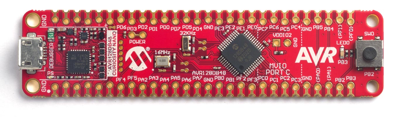
AVR128DB48 Curiosity Nano
Microchip's AVR128DB48 Curiosity Nano evaluation board [3] makes a very low-cost platform for running uLisp.
The board includes a debugger, providing a USB-to-serial interface, which is connected to Serial3:
It's available from suppliers such as Farnell [4].
LED
The Curiosity Nano has a yellow LED connected to pin 20 which you can flash with the following program:
(defun blink (&optional x)
  (pinmode 20 :output)
  (digitalwrite 20 x)
  (delay 1000)
  (blink (not x)))
Run it by typing:
(blink)
Exit from the program by entering ~.
You can save the blink program to EEPROM by typing the command:
(save-image)
You can now load it again after a reset by typing:
(load-image)
AVR Version 3.5b of uLisp now uses the flash memory for save-image, allowing you to save the entire workspace.
Button
The Curiosity Nano has a user button connected between pin 21 and GND which you can test with the following program:
(defun test ()
  (pinmode 21 :input-pullup)
  (loop
   (print (digitalread 21))
   (delay 1000)))
Analogue inputs
The AVR DA series chips support 12-bit analogue readings. By default they are 10-bit for compatibility with other Arduino boards, but you can select 12-bit with:
(analogreadresolution 12)
The analogue reference voltage can be selected with analogreference. For example:
(analogreference :internal2v048)
The options are :vdd or :default, :internal1v024, :internal2v048, :internal4v096, :internal2v5, or :external.
In addition to specifying a pin number to analogread you can also specify one of the following keywords:
- :adc-dac0 reads the value being output by DAC0.
- :adc-temperature reads the internal temperature sensor.
Analogue outputs
The Curiosity Nano can generate an analogue output using PWM on any of the digital pins 4, 5, 8 to 19, 38, or 39.
Note
You can use the note function with Arduino pins 38 and 39, which are available on the edge connector pins PF4 and PF5 respectively. The following example plays the scale of C on a piezo speaker connected to PF4 and GND:
(defun scale ()
  (mapc
   (lambda (n) (note 38 n 4) (delay 500))
   '(0 2 4 5 7 9 11 12))
  (note))
Serial
The Curiosity Nano has one serial port on pin numbers 0 (RX) and 1 (TX).
SPI
The Curiosity Nano has one SPI port on pin numbers 12 (MISO), 11 (MOSI), and 13 (SCK). The clock can be between 125 kHz and 8 MHz.
I2C
I2C is available from pins PA2 (SDA) and PA3 (SCL) on the Curiosity Nano edge connector (not the two TWI0 pins shown on the pinout diagram in the Curiosity Nano User Guide). External I2C devices can be powered by connecting them to VBUS and GND on the Curiosity Nano edge connector.
Multi-Voltage I/O
The AVR128DB48 provides eight I/O pins with Multi-Voltage I/O (MVIO), allowing them to operate at a different voltage from the positive supply.
To use the MVIO you need to change the MVIO on PORTC option on the Arduino IDE Tools menu to Enabled, and do Burn Bootloader to configure the fuses. You can then provide a voltage on the VDDIO2 pin which will act as the high level voltage for pins on PORTC, corresponding to Arduino pins 14 (PC0) to 21 (PC7).
- ^ AVR128DA48 Curiosity Nano User Guide on Microchip.
- ^ DM3164151 - Evaluation Board, Curiosity Nano, AVR128DA48 on Farnell.
- ^ AVR128DB48 Curiosity Nano Hardware User Guide on Microchip.
- ^ EV35L43A - Evaluation Board, Curiosity Nano, AVR128DB48 on Farnell.