Other ESP32 boards
The ESP32 is a series of low-cost, low-power microcontrollers with integrated Wi-Fi and dual-mode Bluetooth, developed by the Chinese company Espressif Systems. It's a successor to their ESP8266 microcontroller. It's based on an Xtensa dual-core (or single-core) 32-bit LX6 microprocessor, operating at 160 or 240 MHz, and features 4 Mbyte of flash and 520 Kbytes of RAM.
The ESP32 version of uLisp uses some of the flash memory to emulate EEPROM, so on all the ESP32 boards you can save the workspace using (save-image).
Update
14th August 2024: This description has been updated to reflect the fact that ESP uLisp Release 4.6c now allows you to use the PSRAM for the Lisp workspace, giving a workspace of 260000 objects.
Boards
General features
LittleFS and save-image
The ESP32 version of uLisp now uses LittleFS to allow you to save the entire workspace on all ESP32 boards using (save-image).
The first time you call save-image LittleFS allocates the file system, and an error may be displayed such as:
./components/esp_littlefs/src/littlefs/lfs.c:1071:error: Corrupted dir pair at {0x0, 0x1}
E (62578) esp_littlefs: mount failed,  (-84)
E (62579) esp_littlefs: Failed to initialize LittleFS
It should subsequently work without error.
Wi-Fi
For examples of using the Wi-Fi features see Wi-Fi examples, and for reference information see Wi-Fi extensions.
Using the register command
As of Version 4.1 of uLisp you can access the ESP32 registers directly with the register command.
On the ESP32 there are 34 GPIO pins: 0-19, 21-23, 25-27, and 32-39. A GPIO Matrix allows you to route any pin to a specified signal within the processor. However, for simple GPIO input and output there are direct ways of accessing or controlling the pins, which is what the following example uses [1]:
Simple GPIO output
The GPIO Matrix can also be used for simple GPIO output. Setting a bit in the GPIO_OUT register will write to the corresponding GPIO pad, where its address is given by:
(defvar gpio-out #x3FF44004)
To configure a pin for simple GPIO output you need to set the GPIO Matrix GPIO_FUNCx_OUT_SEL register to the special peripheral index value #x100. The following function gpio-func-out-sel returns the correct address for this register for pin n, where n is 0 to 39:
(defun gpio-func-out-sel (n) (+ #x3FF44530 (* 4 n)))
You also need to set the appropriate bit in the GPIO_ENABLE register, given by:
(defvar gpio-enable #x3FF44020)
For example, the Adafruit ESP32 Feather has an LED connected to GPIO pin 13. The following program configures this pin and then flashes the LED:
(defun flash ()
  (register (gpio-func-out-sel 13) #x100) ; simple output
  (register gpio-enable (ash 1 13)) ; enable output
  (loop
   (register gpio-out (logxor (register gpio-out) (ash 1 13)))
   (delay 1000)))
DOIT ESP32 DEVKIT V1
The DOIT ESP32 DEVKIT V1 was one of the first ESP32 boards available [2]:
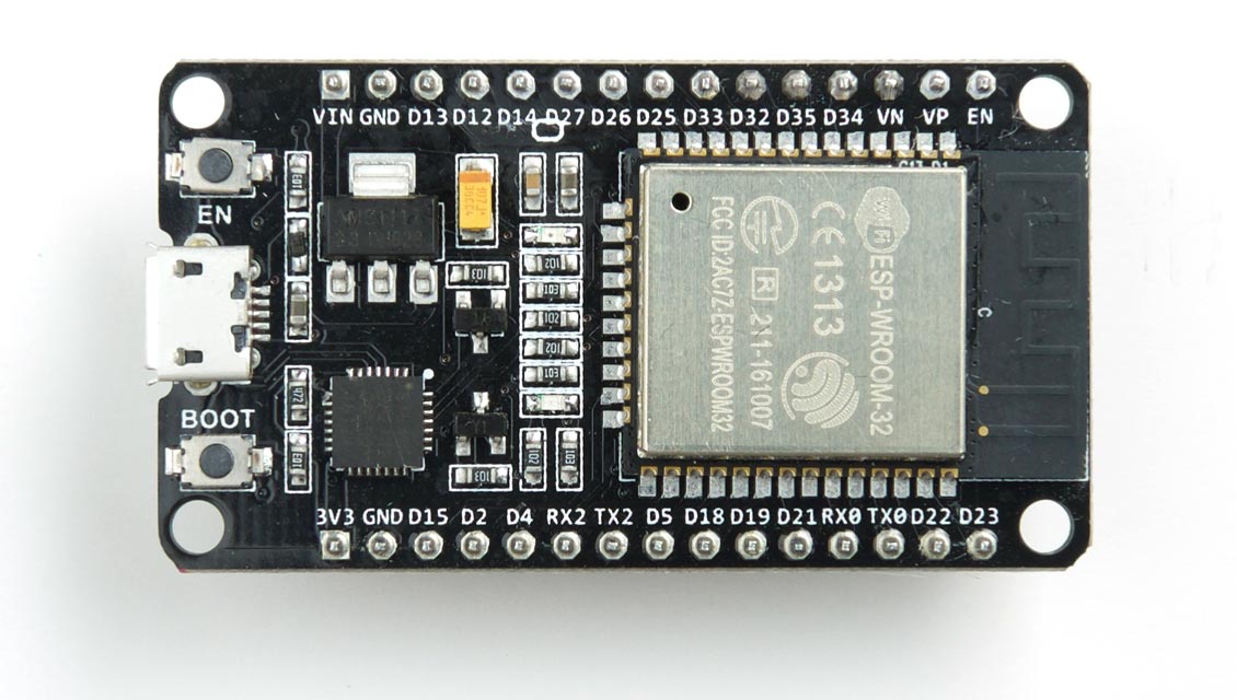
It's based on the ESP-WROOM-32 version of the ESP32, and uses the Silicon Labs CP2102 USB to serial chip for USB connectivity.
Installing uLisp from the Arduino IDE
- Install the ESP32 Arduino core version 2.0.3 or later.
- Select ESP32 Arduino from the Board menu.
- Select the DOIT ESP32 DEVKIT V1 board option.
You can leave the other options at their defaults.
LEDs
The DOIT ESP32 DEVKIT V1 has a blue LED connected to the digital pin 2 which you can flash with the following program:
(defun blink (x)
  (pinmode 2 t)
  (digitalwrite 2 x)
  (delay 1000)
  (blink (not x)))
Run it by typing:
(blink t)
Exit by entering ~.
Wemos ESP32 OLED Module
This Wemos ESP32 module [3] features an integrated I2C monochrome 0.96" 128x64 OLED display:
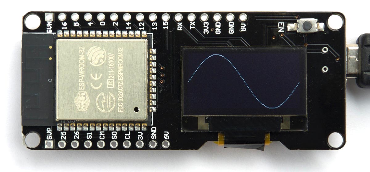
Again, it's based on the ESP-WROOM-32 version of the ESP32, and appears to use the Silicon Labs CP2102, although there are no markings on the chip on my sample board.
In the Arduino IDE use the WEMOS LOLIN32 option on the Board menu.
There is no on-board user LED.
Note that the I2C display is connected to pins 5 (SDA) and 4 (SCL), so you need to edit the lolin32/pins_arduino.h file to:
static const uint8_t SDA = 5;
static const uint8_t SCL = 4;
Wemos ESP32-WROVER
Unlike the other boards tested here the Wemos ESP32-WROVER [4] is based on the ESP32-WROVER module, which includes an additional 4 Mbytes of PSRAM which uLisp uses to provide 260000 objects of workspace:
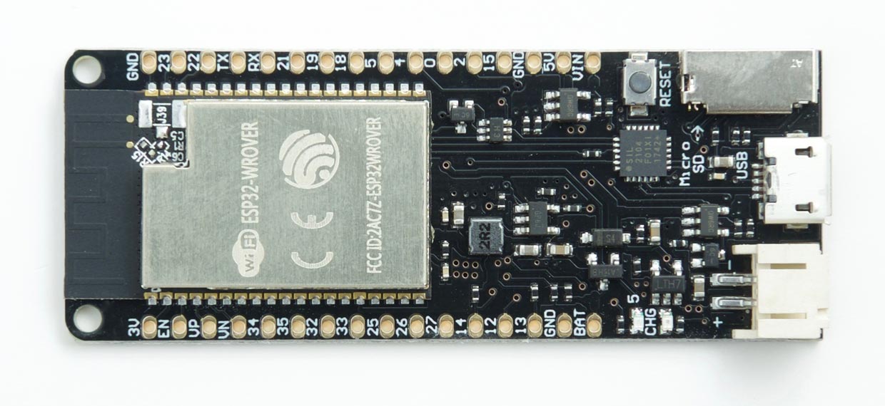
It uses the Silicon Labs CP2104 USB to serial chip for USB connectivity. It also includes a Micro-SD card socket, and a JST socket for a Lipo battery.
To use the board with an SD card you need to edit the appropriate pins_arduino.h file to make the SPI pins correspond to the connections on the SD card socket:
static const uint8_t SS    = 13;
static const uint8_t MOSI  = 15;
static const uint8_t MISO  = 2;
static const uint8_t SCK   = 14;
DSTIKE D-duino-32
This was an ideal ESP32 board for use with uLisp, but unfortunately is no longer available:
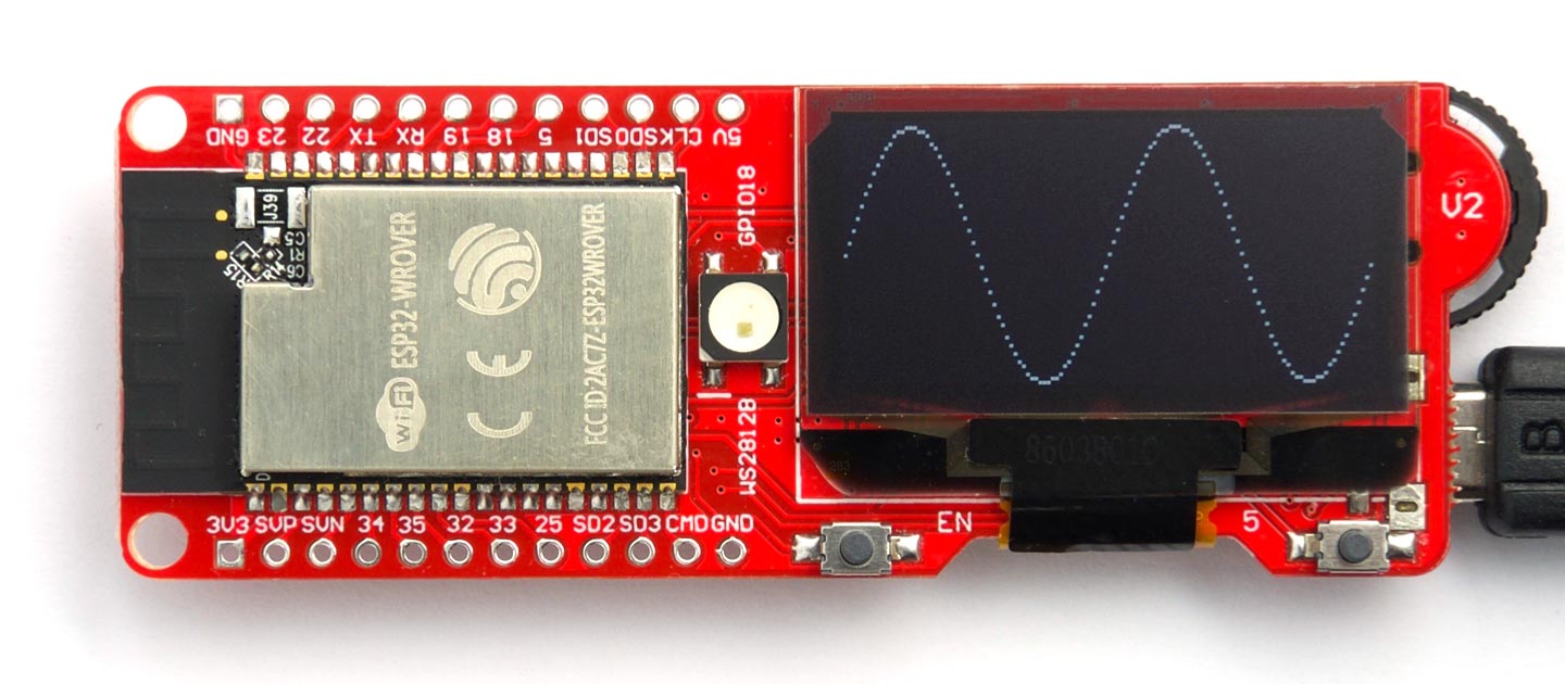
It has the following features:
- ESP32 WROVER module
- microSD card socket
- JST LiPo connector.
- Battery charging via USB.
- Monochrome 1.3" 128x64 OLED.
- 3-way control switch
- WS2812b RGB LED
The WROVER module includes an additional 4 Mbytes of PSRAM which uLisp uses to provide 260000 objects of workspace.
It uses the Silicon Labs CP2102 USB to serial chip for USB connectivity.
To use it with the Arduino IDE select the ESP32 Wrover Module board setting.
microSD cards
To use the board with an SD card you need to change the SPI pin settings to correspond to the connections on the SD card socket. The easiest way is to edit the esp32/pins_arduino.h file:
static const uint8_t SS    = 13;
static const uint8_t MOSI  = 15;
static const uint8_t MISO  = 2;
static const uint8_t SCK   = 14;
You should then be also to run all the examples in SD card interface.
Buttons
The board includes a navigation switch with the following connections:
- Up: pin 32
- Select: pin 33
- Down: pin 25
There are also two buttons below the display:
- Left: EN
- Right: pin 5
RGB LED
The board has a WS2812b RGB LED connected to pin 18.
OLED display
The board includes a 128x64 OLED display, which is based on the SH1106 driver chip. Note that the I2C display is connected to pins 26 (SDA) and 27 (SCL), so you need to edit the esp32/pins_arduino.h file to:
static const uint8_t SDA = 26;
static const uint8_t SCL = 27;
Here's a simple program to initialise the display, and then plot a function on the display:
(defvar *address* 60)

(defvar *commands* #x00)

(defvar *data* #x40)

(defun write-many (s &rest b)
  (dolist (i b) (write-byte i s)))

(defun init-display ()
  (with-i2c (s *address*)
    (write-many s *commands* #xA1 #xAF)))

(defun plot (x y)
  (incf x 2)
  (dotimes (p 8)
    (with-i2c (s 60)
      (write-many s #x80 (+ #x00 (logand x 15)) #x80
                  (+ #x10 (ash x -4)) #x80 (+ #xB0 p) #xc0)
      (if (<= 0 y 7)
          (write-byte (ash 1 y) s)
        (write-byte 0 s)))
    (setq y (- y 8))))

(defun test ()
  (init-display)
  (dotimes (x 128)
    (plot x (round (+ 31 (* 31 (sin (* x (/ (* 2 3.14) 64)))))))))
The routine (plot x y) plots a point on the display, where x can be from 0 to 127 and y from 0 to 63, and (plot 0 0) is the lower left-hand corner. Note that plot can only plot a function; ie only one point can be plotted in each column. The routine (test) plots two cycles of a sine wave.
For a more comprehensive graphics package that will also work on this display see Graphics display interface in Lisp.
Acknowledgements
I'm grateful to Klaus Fuerth for help completing the ESP32 version, and in particular the SD Card support.
- ^ ESP32 Technical Reference Manual on Espressif.com.
- ^ DOIT ESP32 Development Board on Aliexpress.
- ^ Wemos ESP32 OLED Module on Banggood.
- ^ Wemos ESP32-WROVER on Banggood.