RP2040 boards
The RP2040 is a microcontroller chip designed by Raspberry Pi in the UK. It's a dual-core ARM Cortex M0+ running at 133 MHz which provides up to 16 MB of off-chip flash and 246 KB on-chip RAM. It has 30 GPIO pins, 4 of which can be used as analogue inputs, two UARTs, two SPI controllers, two I2C controllers, and 16 PWM channels.
Raspberry Pi also released a board based on the chip, called the Raspberry Pi Pico. Other manufacturers soon followed suit, including Adafruit, Sparkfun, Seeed Studio, and Pimoroni who have also designed boards based on the RP2040. These boards all have similar performance when running uLisp.
Boards
Introduction
Originally I recommended the Arduino Mbed OS RP2040 Boards core for the Raspberry Pi Pico, but you should now use Earle Philhower’s Raspberry Pi Pico/RP2040 Arduino core [1] which supports a wide range of RP2040 boards, supports more Serial, SPI, and I2C ports, and gives significantly better performance. See the installation instructions below.
Saving the workspace
The Raspberry Pi Pico and other RP2040 boards use the LittleFS flash filesystem supported by the Raspberry Pi Pico/RP2040 core to allow you to save the entire workspace using save-image.
ARM assembler
The ARM version of uLisp includes an ARM assembler that allows you to generate machine-code functions, integrated with Lisp, written in ARM thumb code. The assembler itself is written in Lisp to make it easy to extend it or add new instructions. For more information see ARM assembler overview.
Programming the RP2040 registers
For details of directly programming the RP2040 registers from uLisp see Programming ARM registers.
Installing uLisp from the Arduino IDE
Install the Raspberry Pi Pico/RP2040 core
- Add the following URL to the Additional Boards Manager URLs list in the Arduino IDE Preferences dialog box:
https://github.com/earlephilhower/arduino-pico/releases/download/global/package_rp2040_index.json
- In the Arduino IDE search for the Raspberry Pi Pico/RP2040 core in Boards Manager and install it.
- Select Raspberry Pi RP2040 Boards from the Board menu, and the appropriate board from the submenu.
- Set Flash Size to the option that gives FS: 1MB. On the Raspberry Pi Pico this is 2MB (Sketch: 1MB, FS: 1MB).
This allocates enough space for use by LittleFS to save the entire workspace with save-image.
You can leave all the other options at their defaults.
Upload uLisp
- Download the latest ARM version of uLisp from the Download uLisp page.
- Select the board's USB port from the Port menu
- Upload uLisp to the board.
Using uLisp
- You may need to select the board's USB port from the Port menu again.
- Select Serial Monitor from the Tools menu.
- Enter Lisp commands.
Putting the board into upload mode
If the upload fails you may need to put the board into upload mode first.
On boards with a reset button, such as the Adafruit boards:
- Press and hold the Boot or B button.
- Press the Reset or R button.
- Release the Boot button.
On boards without a reset button, such as the Raspberry Pi Pico:
- Unplug the USB port.
- Press and hold the Boot button.
- Plug in the USB port.
- Release the Boot button.
Error on save-image
If when you call save-image you get the error;
Error: 'save-image' problem saving to LittleFS
the most likely explanation is that you didn't set the Flash Size option to the appropriate value to reserve memory for LittleFS before uploading uLisp.
Raspberry Pi Pico
The Raspberry Pi Pico [2] is about the same size as Adafruit's Feather boards:
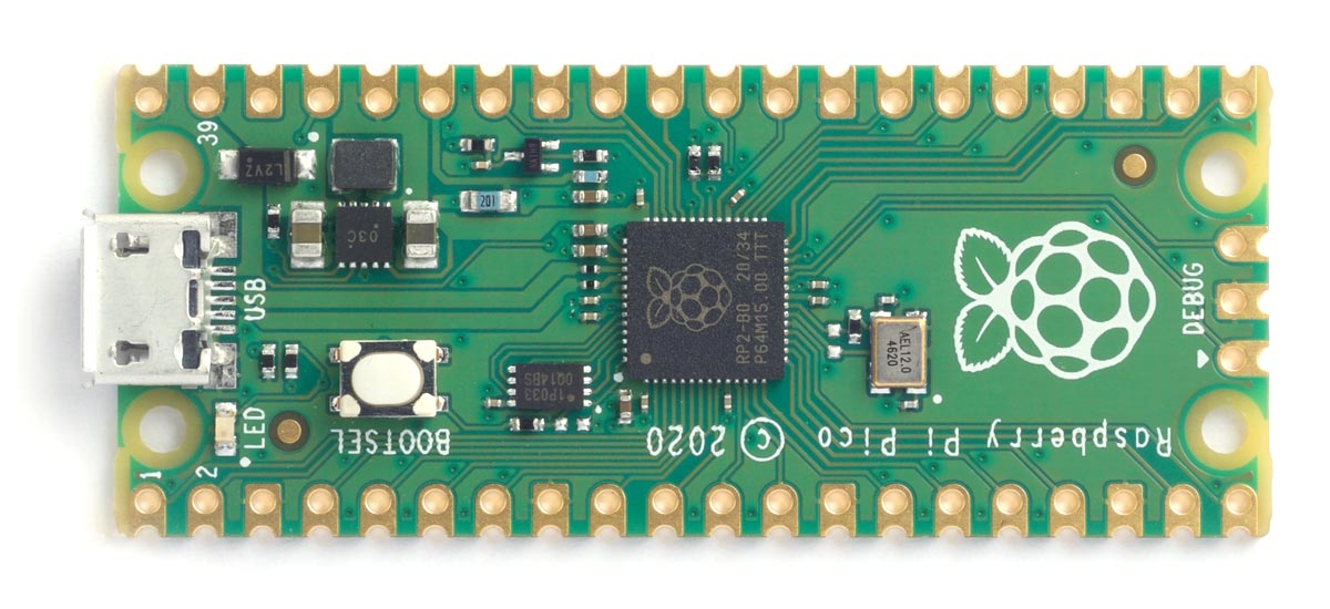
The Raspberry Pi Pico board includes 2 MByte of flash, and gives access to two serial ports (in addition to Serial0 used for the USB interface), two SPI ports, and two I2C ports.
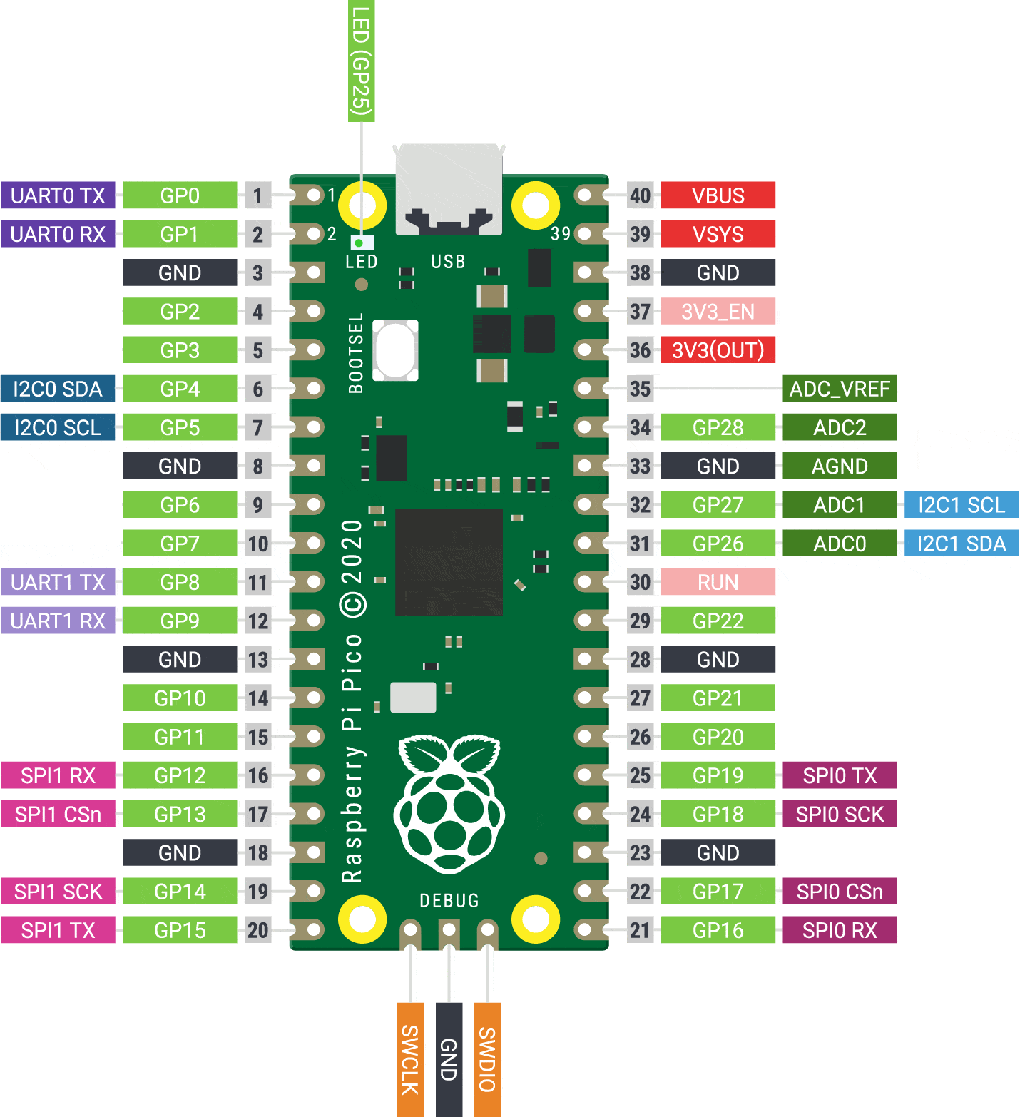
Pinout
The following diagram shows the pinout of the peripherals available from uLisp with the Raspberry Pi Pico:
LEDs
The Raspberry Pi Pico has a green LED connected to the digital pin 25 which you can flash with the following program:
(defun blink (&optional x)
  (pinmode :led-builtin t)
  (digitalwrite :led-builtin x)
  (delay 1000)
  (blink (not x)))
Run it by typing:
(blink)
All pins can also be used for analogue (PWM) output, so you can pulsate the LED slowly on and off with the program:
(defun pulse ()
  (let (down)
    (loop
     (dotimes (x 256)
       (delay 5)
       (analogwrite :led-builtin (if down (- 255 x) x)))
     (setq down (not down)))))
Run it by typing:
(pulse)
Exit from either program by entering ~.
Analogue inputs
The Raspberry Pi Pico has three analogue inputs which you can access on digital pins 26, 27, and 28. They have 12-bit precision.
Analogue outputs
You can generate an analogue output using PWM on any of the digital pins 0 to 28. By default the precision is 8 bits, but you can change it to a value from 4 to 16 bits by calling, for example:
(analogwriteresolution 16)
Playing notes
You can use the note function to play tunes on any pin. For example, the following function scale plays the scale of C on the specified pin:
(defun scale (pin)
  (mapc
   (lambda (n) (note pin n 4) (delay 500))
   '(0 2 4 5 7 9 11 12))
  (note))
For example, connect a piezo speaker between digital pin 10 and GND, and evaluate:
(scale 10)
Serial
The Raspberry Pi Pico has two serial ports: Serial1 on pin numbers 0 (TX) and 1 (RX), and Serial2 on pin numbers 8 (TX) and 9 (RX).
SPI
The Raspberry Pi Pico has two SPI ports: SPI0 on pin numbers 16 (MISO), 19 (MOSI), 18 (SCK) and 17 (SS), and SPI1 on pin numbers 12 (MISO), 15 (MOSI), 14 (SCK) and 13 (SS).
I2C
The Raspberry Pi Pico has two I2C ports: Wire0 on pin numbers 4 (SDA) and 5 (SCL), and Wire1 on pin numbers 26 (SDA) and 27 (SCL).
Raspberry Pi Pico W
The Raspberry Pi Pico W [3] adds Wi-Fi wireless networking to the Pico while retaining pin compatibility with the earlier board:
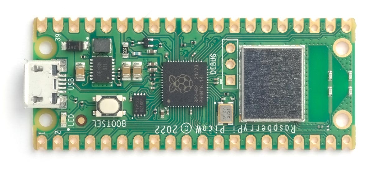
The wireless networking uses an Infineon CYW43439 to provide 802.11n single-band 2.4 GHz Wi-Fi with WPA3 and Soft Access Point supporting up to 4 clients.
For details of the uLisp Wi-Fi extensions see Wi-Fi extensions.
For examples see Wi-Fi examples.
All the other features are identical to the Raspberry Pi Pico, apart from the fact that you cannot use the (pulse) example to give analogue output to the built-in LED.
Adafruit Feather RP2040
Adafruit have made an RP2040-based board in their Feather format [4]. It includes a NeoPixel LED and an 8 MByte DataFlash chip:
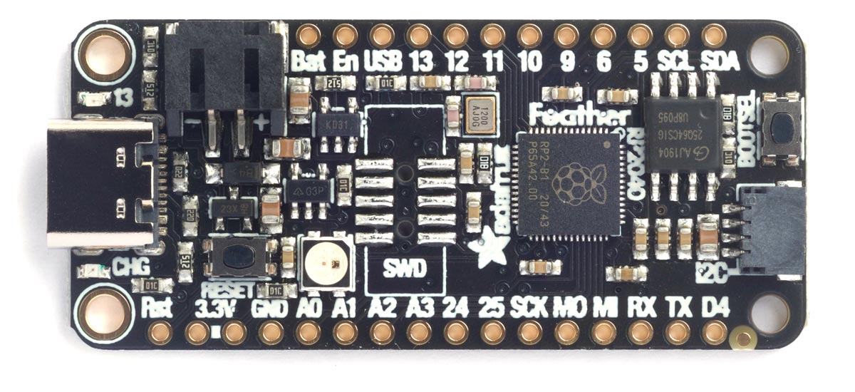
The latest version of their board is pink. A Stemma QT connector lets you daisy-chain I2C sensors and displays.
LED
The Adafruit Feather RP2040 has a red LED connected to the digital pin 13 which you can flash with the following program:
(defun blink (&optional x)
  (pinmode :led-builtin t)
  (digitalwrite :led-builtin x)
  (delay 1000)
  (blink (not x)))
Run it by typing:
(blink)
All pins can also be used for analogue (PWM) output, so you can pulsate the LED slowly on and off with the program:
(defun pulse ()
  (let (down)
    (loop
     (dotimes (x 256)
       (delay 5)
       (analogwrite :led-builtin (if down (- 255 x) x)))
     (setq down (not down)))))
Run it by typing:
(pulse)
Exit from either program by entering ~.
Analogue inputs
The Adafruit Feather RP2040 has four analogue inputs which you can access on digital pins 26 to 29. They have 12-bit precision.
Analogue outputs
You can generate an analogue output using PWM on any of the digital pins 0 to 29. By default the precision is 8 bits, but you can change it to a value from 4 to 16 bits by calling, for example:
(analogwriteresolution 16)
Playing notes
You can use the note function to play tunes on any pin. For example, the following function scale plays the scale of C on the specified pin:
(defun scale (pin)
  (mapc
   (lambda (n) (note pin n 4) (delay 500))
   '(0 2 4 5 7 9 11 12))
  (note))
For example, connect a piezo speaker between digital pin 10 and GND, and evaluate:
(scale 10)
Serial
The Adafruit Feather RP2040 has one accessible serial port: Serial1 on pin numbers 0 (TX) and 1 (RX).
SPI
The Adafruit Feather RP2040 has one accessible SPI port: SPI0 on pin numbers 20 (MISO), 19 (MOSI), 18 (SCK) and 17 (SS).
I2C
The Adafruit Feather RP2040 has one accessible I2C port: Wire1 on pin numbers 2 (SDA) and 3 (SCL), which also go to the Stemma QT connector.
- ^ Raspberry Pi Pico/RP2040 Arduino core on GitHub.
- ^ Raspberry Pi Pico on Adafruit.
- ^ Raspberry Pi Pico W on Adafruit.
- ^ Adafruit Feather RP2040 on Adafruit.